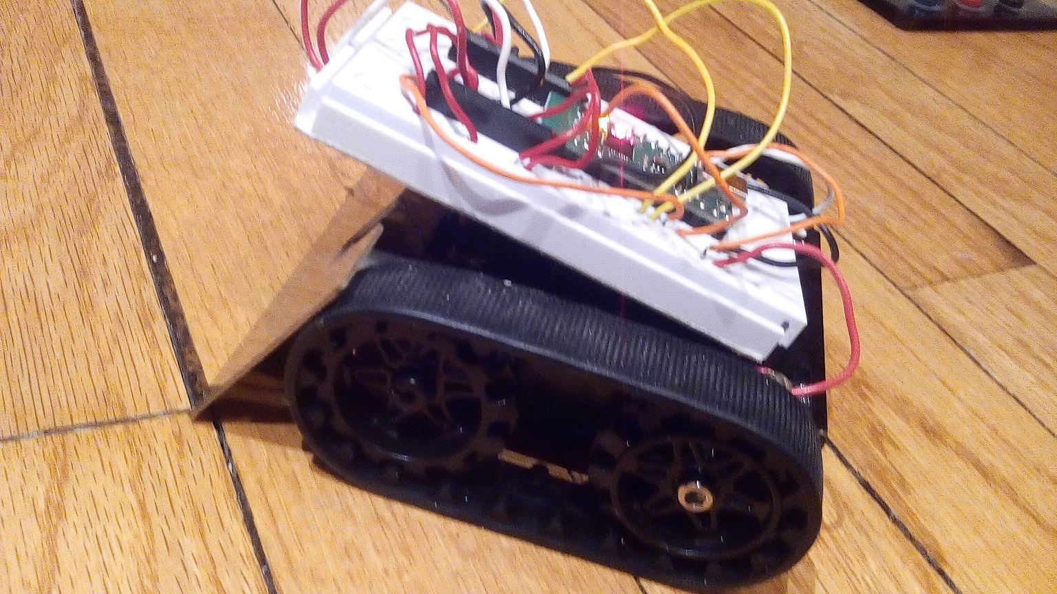
I made this simple remote controlled robot using a pair of Wixels (with no micro controllers) on a set of 170 pin bread boards. (I may make some PCBs with chip sockets to make it more permanent and durable). On the robot, I used a pair of BA6886N motor driver chips to run a pair of 75:1 motors in a bare bones Zumo kit.
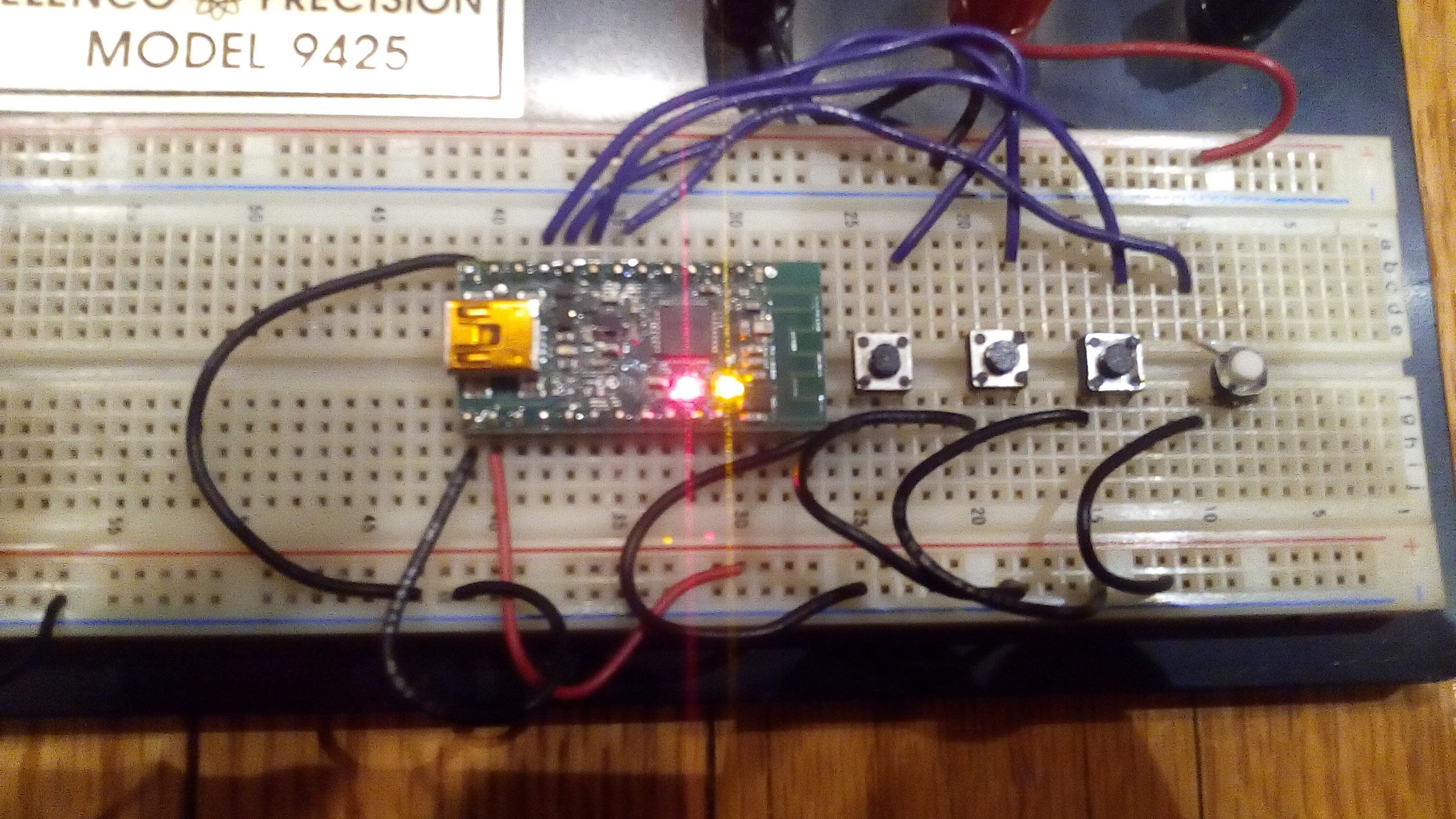
For the controller, I hooked up 4 tactile push button switches to P1_2 to P1_5 on a Wixel with all switches going to ground.
On the robot, I set up the other Wixel and tested it first using four LEDs with 100ohm resistors hooked up to the outputs (P1_2 to P1_5) to ensure the system worked before installing the motor drivers.
I used the I/O Repeater app from the Wixel user manual and just had to configure and upload one version for the Wixel on the controller:
P1_2 = -1
P1_3 = -2
P1_4 = -3
P1_5 = -4
And one for the robot:
P1_2 = 1
P1_3 = 2
P1_4 = 3
P1_5 = 4
(The negative values set the mode of the pins as inputs for the first Wixel --on the controller. The same pins on the other Wixel --on the robot are conversely set as outputs using positive values of the same numbers).
The way the BA6886N’s need to be wired are as follows:
Left Motor Driver
Pin 1 = Gnd (from a 4AA battery pack)
Pin 2 = P1_2 (from the robot’s Wixel)
Pin 3 = Vcc (+6 volts from a 4AA battery pack)
Pin 4 = Left motor lead 1
Pin 5 = Gnd
Pin 6 = Gnd
Pin 7 = Left motor lead 2
Pin 8 = Vcc
Pin 9 = Vcc
Pin 10 = P1_3 (from the robot’s Wixel)
**(good to put a small electrolytic capacitor between Pin 9 and ground: attach negative lead (-) (white stripe) on capacitor to ground; positive (+) lead goes to Pin 9 along with Vcc.
***Also good to eliminate electrical noise on the motors by soldering a few .1 uF ceramic capacitors (104) across the motor leads. Check where you are putting them so that they still fit in the Zumo’s case.
Right Motor Driver
Pin 1 = Gnd (from a 4AA battery pack)
Pin 2 = P1_4 (from the robot’s Wixel)
Pin 3 = Vcc (+6 volts from a 4AA battery pack)
Pin 4 = Right motor lead 1
Pin 5 = Gnd
Pin 6 = Gnd
Pin 7 = Right motor lead 2
Pin 8 = Vcc
Pin 9 = Vcc
Pin 10 = P1_5 (from the robot’s Wixel)
Hope you find this useful as a start for your own projects–good luck!