Since there is no library, yet, for PWM I thought I would share my progress/findings for anyone else that is playing with PWM on the Wixel.
After a quick search of the CC2511 page I found a design note that looked helpful, DN115 – Using PWM for Dimmer Function in LED Lighting.
But after trying the code and some head scratching as to why it was not working and more google searches, I eventually came across a forum post about a similar chip the CC2530 and PWM - http://e2e.ti.com/support/low_power_rf/f/156/p/118346/428582.aspx. The code is rather similar so figured that I was on the right track so decided to examine what was acutally happening with the code from DN115.
After looking at the contents of the registers, before and after, the code in DN115 I found that there is something missing. Timer 1 was not actually enabled, granted there is a comment about setting Timer 1 to Modulo Mode but there is no code that actually does it.
So far I have managed to dim a led by a given value, and rather crudely step a led through a few different dim levels.
Without further ado, the registers that need to be altered to get it to work:
/* PWM freq = 13M / 128 / 511 = 198.75 Hz /*
T1CC0L = 0xff;
T1CC0H = 0x01;

// PWM duty cycle about 1/8
T1CC1L = 0x3F;
T1CC1H = 0x00;

/* Timer 1 channel 1 set compare mode 4 */
T1CCTL1 |= 0x24;

/* Prescaler set to Tick Freq / 128 */
T1CTL |= 0x0c;

/* Timer 1 CFG set to Alt 2 location */
PERCFG |= 0x40;

/* P1_1 set peripheral func which associated with Timer 1 output */
P1SEL |= 0x2;

/* set modulo mode */
T1CTL |= 0x02;
The two lines changing T1CTL can be merged, they are just separate as I was playing with different changes to get it to work.
With this knowledge ideally I would like to write a library for controlling PWM, I’m thinking of something similar to the analogWrite function that the Arduino has http://arduino.cc/en/Reference/AnalogWrite.
Hello!
Thank you for posting your working and well-commented PWM code!
If you want to write a library, the best way to share your library with the community would be to fork the wixel-sdk repository on github.
Also, I suggest making your library better than the Arduino’s by choosing a better name than “analogWrite()” for the function. Neither the Arduino nor the Wixel actually have a DAC, so a more appropriate name would be something like pwmConfig() or t1PwmConfig().
–David
Just a quick update about the library for PWM.
After some thinking about the best way to go about this I came to the conclusion that a timer library is needed first, mainly for a couple of reasons: it will make doing hardware and software PWM easier; and I’m sure other people will find it helpful. So that is where I have started.
So far I have a number of the Timer 1 functions done, though I have not done the calculations for the up/down timer mode yet. Some of the functions have somethings implemented for TImer3/4 but I really need to spend some time really reading the datasheet to make sure everything is correct. Also I have not done anything about using interrupts yet, as I want to get everything else working first.
If anyone wants to have a play with it https://github.com/dpark83/wixel-pwm, if you find something that does not work just (or you can see how to improve anything) let me know and I’ll try to fix it. BTW there is a test app that basically does hardware PWM with a led.
I do have a question about up/dowm timer mode: since it counts up to T1CC0 (for Timer 1) and then back down to 0, is it correct that the output would have twice the period of using the modulo timer mode with the same T1CC0?
Another quick update about a success that I’ve had with software PWM, well still using a timer but using an ISR to control the pulses.
#include <wixel.h>
#include <usb.h>
#include <usb_com.h>
#include <stdio.h>

/* VARIABLES ******************************************************************/
uint8 XDATA response[32];
PDATA volatile uint32 pwmCounter = 0; /* ticks of the pwm timer */
PDATA uint8 pwmPeriod = 200; /* how long the pwm wave lasts for: 20ms @ 10KHz */
PDATA volatile uint32 pwmPeriodNext = 200; /* when the next pwm period starts*/
PDATA volatile uint8 pwmPulse = 15; /* how long the pwm pulse last for: 1.5ms @ 10KHz */
PDATA volatile uint32 pwmPulseEnd = 15; /* when the pwm pulse ends */

/*
  Pulse
   ###
   ###
   ###
   ########################################
                  Period
*/

/* FUNCTIONS ******************************************************************/
ISR(T3, 2) {
	pwmCounter++;
	if (pwmCounter == pwmPeriodNext) {
		setDigitalOutput(P0_1, HIGH);
		pwmPulseEnd = pwmCounter + pwmPulse;
		pwmPeriodNext += pwmPeriod;
	} else if (pwmCounter == pwmPulseEnd) {
		setDigitalOutput(P0_1, LOW);
	}
}

void updateLeds() {
    usbShowStatusWithGreenLed();
}

void processByte(uint8 byteReceived) {
    uint8 responseLength;
    switch(byteReceived) {
	case 'q':
		pwmPulse++;
        responseLength = sprintf(response, "pwmPulse=%d\r\n", pwmPulse);
        usbComTxSend(response, responseLength);
		break;
	case 'a':
		pwmPulse--;
        responseLength = sprintf(response, "pwmPulse=%d\r\n", pwmPulse);
        usbComTxSend(response, responseLength);
		break;
    }
}

void processBytesFromUsb() {
    uint8 bytesLeft = usbComRxAvailable();
    while(bytesLeft && usbComTxAvailable() >= sizeof(response)) {
        processByte(usbComRxReceiveByte());
        bytesLeft--;
    }
}

void softPwmInit() {
    T3CC0 = 75;
    T3IE = 1; // Enable Timer 3 interrupt.

    // DIV=101: 1:32 prescaler
    // START=1: Start the timer
    // OVFIM=1: Enable the overflow interrupt.
    // MODE=10: Modulo
    T3CTL = 0b10111010;
    EA = 1; // Globally enable interrupts.
}

void main() {
    systemInit();
    usbInit();
    softPwmInit();

    while(1)
    {
        boardService();
        updateLeds();
        usbComService();
        processBytesFromUsb();
    }
}
Just a quick explaination about how Timer 3 is setup:
softPwmInit sets up Timer 3 to run at 10KHz and to trigger interrupts.
To know that it is running at 10KHz we use: processor speed/prescaler/compare value
- processor speed: 24,000,000 - (24MHz)
- prescaler: 32 (T3CTL.DIV)
- compare value: 75 - (T3CC0)
24,000,000/32/75=750,000/75=10,000
If you connect to the wixel via USB you can alter the PWM pulse with the q (increase) and a (decrease) keys.
I’ve tested this with some servos and it works a treat, though I’m more interested in using continouse servos so having .1ms resolution works fine with me - about 5 speeds in each direction. Some improvements that I would like to add are converting this into a library and the ability to specify what pin/s to use with eaching having a pulse setting. I’m thinking an array of structs or something like that, ideas/suggestions/etc are welcome.
I’m glad you are having success with the Wixel and PWM. I have a couple of suggestions:
To get consistent pulses out of the Wixel, you should make sure that the servo pulse interrupt is the highest priority interrupt enabled. The systemInit function you are calling enables a timer interrupt for millisecond timing.
Also, you wrote:
setDigitalOutput(P0_1, HIGH); // Incorrect!
Unforunately, this is wrong. You should do this instead:
setDigitalOutput(1, HIGH); // correct
or if you configured the pin as an output earlier you can simply do
P0_1 = 1
–David
Thanks for the suggestions and corrections (I should really know better than to code while tired).
Just want to double check my reading of the datasheet about priorities:
To adjust the prioirty level of Timer 3, bit 3 of IP0 (IP0_IPG3) and IP1 (IP1_IPG3) need to be changed since Timer 3 is in Interrupt Priority group 3.
If both of these bits are set to 1 then it will be given the highest priority level.
Yes, that is correct. Unfortunately USART1 is in the same interrupt priority group so you won’t be able to do any interrupt-based use of that UART in the same application.
–David
For my project, I want to use PWM to control a servo. I have used an Arduino with the AnalogWrite function for PWM and this code is at a lower level than what I’m used to so I’m confused. I don’t need to use interrupts because I only want the pulses to occur when a condition is met in my program. Do you think your code could be simplified more? I don’t need to control the speed from my computer. I just want the servo to run at a preset speed.
Thank you! 
Nevermind  – I just emulated the example blink LED program for PWM and it seems to do the job. I got the speed I wanted through trial and error.
#include <wixel.h>
#include <time.h>
#include <usb.h>
#include <usb_com.h>

uint32 lastToggle = 0;

void pwm()
{

    if (getMs() - lastToggle >= 156)
    {

    	setDigitalOutput(1, HIGH); //set analog pin P0_1 high
        lastToggle = getMs();
    }

    else
    {
    	setDigitalOutput(1, LOW);
    }
}


void main()
{
    systemInit();
    usbInit();

    while(1)
    {
        boardService();
        pwm();
        usbComService();
        usbShowStatusWithGreenLed();
        LED_RED(1);
    }
}
Does that code work for controlling your servo? It looks like it drive P0_1 high (3.3 V) briefly once every 156 milliseconds. The amount of time that P0_1 is high will depend on how long your main loop takes to run and how many interrupts occur while it is high. This is not the kind of signal that you would ideally want to generate for controlling a servo. You might want to read this blog post:
pololu.com/blog/17/servo-con … -in-detail
–David
The code did allow the servo to run at different speeds by changing the value in [quote]getMs() - lastToggle >= 156[/quote]. But I would like to understand a better way of doing PWM. I don’t understand how to work off of the code posted that uses an interrupt to constantly apply PWM. I want the servo to only run under certain conditions, like [quote]if (condition > value) { run servo } [/quote] so I want to be able to call a PWM function.
It sounds like you want the ability to stop sending pulses to the servo at certain times. Essentially you want to set the pulse width to 0.
The PWM code posted above by dpark83 does not currently support that case (pwmPulse == 0) but I think you can modify the ISR to support that case:
ISR(T3, 2) {
    pwmCounter++;
    if (pwmCounter == pwmPeriodNext)
    {
        if (pwmPulse)
        {
            setDigitalOutput(1, HIGH);
        }
        else
        {
            setDigitalOutput(1, LOW);  // probably not necessary
        }
        pwmPulseEnd = pwmCounter + pwmPulse;
        pwmPeriodNext += pwmPeriod;
    }
    else if (pwmCounter == pwmPulseEnd)
    {
        setDigitalOutput(1, LOW);
    }
}
Then your application code would look something like:
if (condition > value)
{
    pwmPulse = 15;  // Insert your own code for computing the position here.
}
else
{
    pwmPulse = 0;  // Stop sending pulses to the servo.
}
If you are just controlling one servo though, I would recommend using hardware PWM with Timer 3 instead, but that would involve writing some tricky code which you might not want to do.
–David
dpark83,
I have gotten your code to work on my wixel by changing P0_1, now I have a question. Is it possible to modify this code to generate a 38Khz square pulse for IR communication? I notice in your code it says the pwm runs at 10Khz. I have the data sheet for the CC2511 but I haven’t been able to figure much out. Any help would be greatly appreciated!
I was wondering what the purpose is of using an ISR to control the PWM, as shown above for Timer 3, rather than setting the PWM through the registers as shown above for Timer 1. It seems like they both accomplish the same thing so I was wondering if there are advantages for using one method over another. Also, does the “2” in ISR (T3, 2) mean that the interrupt fires twice per millisecond?
You’re basically asking for a comparison between pure hardware PWM, and software PWM with the aid of a timer interrupt. The hardware PWM will be more accurate and take less CPU time, but it is tied to specific pins of the Wixel. The software PWM can operate on multiple pins of the Wixel, so you could expand it to control many servos with a single timer.
The number 2 in that context says that the code in the interrupt will use register bank 2. There are 4 register banks (0-3). The ISR macro is defined in cc2511_map.h. For more information, see:
sdcc.sourceforge.net/doc/sdccman … ode76.html
–David
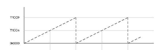
I have some questions about the register settings for hardware PWM. In reference to the first post about hardware PWM with Timer 1, why is output compare mode 4 used with the Modulo mode? Output compare mode 4 is in the TI documentation as “Clear output on compare-up, set on 0 (set on compare-down in up/down mode)”. In the TI design note called “Using PWM for Dimmer Function in LED lighting”, there’s a diagram of the pulse width in Modulo mode that is unclear to me. This diagram is attached. I understand that T1CC0 stores the compare value, but I don’t understand what “T1CCn” refers to, and it’s distinguished from T1CC0.
I’m trying to understand how to set the frequency and duty cycle using Timer 3 PWM. I have been using this code without realizing what the frequency/duty cycle really are:
void pwmInit() { //configure Timer 3 Channel 0 for servo's PWM

	T3CTL = 0xB2; // divides the 24 MHz counter by 32, Modulo mode
	T3CC0 = 0xFE; //Timer 3 Channel 0 compare value
	T3CCTL0 = 0x24; // Timer 3 Channel 0 Compare Mode 4
	P1SEL = 0x8; // configure P1_3 as a peripheral pin associated with Timer 3 Channel 0 output

}
There are three compare channels associated with Timer 1, so you can have three different pulse widths at the same repetition rate. From the CC2511f32 datasheet:
[quote]Note: In the following sections, an n in the
register name represent the channel
number 0, 1, or 2 if nothing else is stated[/quote]
As I understand the diagram, the “n” represents one of the other channels, which results in a shorter pulse width than would be derived from channel 0. See the rest of Figure 33.
For eight bit Timer 3, there are two channels, 0 and 1. Eight bit timers don’t work well for servos because of the poor pulse width resolution.
Output compare mode is used to generate a PWM signal. The compare value determines how long it takes for the comparison to happen, so it determines the high time of the pulse (or low time, depending how the timer is configured).
Modulo mode is used so you can have control over the frequency of the PWM signal. By specifying when the timer resets, you specify the frequency.
By the way, I made a new servo library for the Wixel that might want to use:
pololu.github.com/wixel-sdk/servo_8h.html
–David
Thank you for the information. The TI documentation still isn’t quite clear because you wouldn’t know which of the two other channels the “n” represents. I don’t understand why it even worked when I used Timer 3 because I only specified one output compare value through T3CC0. I have a few more questions about this:
-
Eight bit timers don’t work well for servos because of the poor pulse width resolution.
The servo I have is modified for continuous rotation, so I was wondering how its performance would be affected by pulse width resolution.
-
Most servo data sheets specify “50 Hz” but they can apparently be run at a much higher frequency. Is it good to run a servo at a high frequency? How can you determine the optimal frequency? I’m trying to find an explanation about why when I increased the servo frequency beyond a level, it would only run clockwise and not counterclockwise. It has much better torque at this frequency though. When I increased the frequency even more, the servo wouldn’t move at all.
I will definitely look into the new servo library. Thanks!!
The “n” specifies any of the channels. The point is that Timer 1 has three different channels which all have the same interface. Since all channels are pretty much the same, the writers at TI wanted a concise way to write sentences that describe all the channels at once. For example, section 12.6.4 of the datasheet says “The contents of the 16-bit capture register can be read from registers T1CCnH:T1CCnL.” This is a shortcut for saying: “The contents of 16-bit capture registers for channels 0, 1, and 2 can be read from registers T1CC0H:T1CC0L, T1CC1H:T1CC1L, and T1CC2H:T1CC2L respectively.”
It doesn’t sound like you’re trying to do precise speed control with these servos so your pulse width resolution doesn’t matter too much.
Since your pulse frequency affects the torque, it sounds like you are using an analog servo. You can learn more about this affect and why it is happening by reading this blog post by Jan:
pololu.com/blog/17/servo-con … -in-detail
Jan did a whole series of blog posts about servos and I recommend reading them all.
–David
