I want to measure the position of a potentiometer (or another variable resistor) using one of the maestro channels. The manual gives an example of how to wire this: Pololu - 7.b. Attaching Servos and Peripherals The example in the manual uses the regulated 5Vout pin on the board to supply the input.
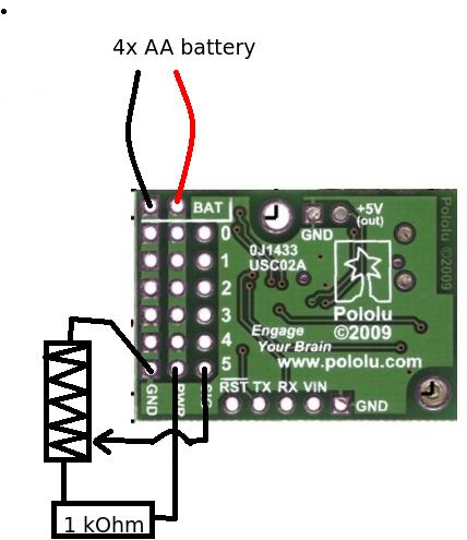
However, I was wondering whether it is possible to use the pins that supply voltage to the servos to supply power. I am powering the servos with a 4 AA battery pack (i.e. max 6V). The image below depicts the setup I have in mind. The maximum voltage would be about 6V, with a minimal resistance of 1kOhm, this would result in a current of 6mA. Would this be acceptable for the signal line?
The maximum voltage the signal pins on the Maestro can handle is 5V, so connecting 6V to them could damage them. In your circuit it looks like you tried to reduce the possible maximum voltage by adding the 1k resistor, but I cannot say whether that is sufficient without knowing the value of your potentiometer. Is there some reason you do not want to use the 5V out pin to power your potentiometer?
Is there some reason you do not want to use the 5V out pin to power your potentiometer?
Well, I thought it might be easier to wire separate potentiometers to different pins. And also, I (wrongly?) assumed that wiring a second potentiometer to the same 5V pin would influence the reading on the first one. However, after thinking this over, I now believe that this is incorrect and the reading of both potentiometers will be independent.
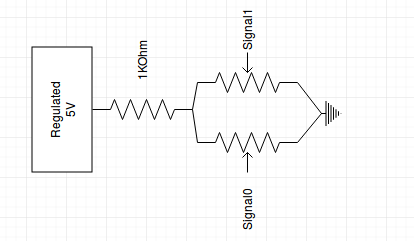
Just to make sure, would the following work: wiring a 1kOhm resistor to the 5V regulated channel and splitting the output of this to two potentiometers, each read out on a different channel of the maestro board? See sketch below.
The problem I am running into is that the readings for both the channels give more or less the same value. Turning the potentiometer or changing the light received by the light sensitive resistors both change the readings in both channels.
Am I doing something wrong in my diagram or am I misunderstanding the way the meastro works?
Your light sensing resistor is probably not the same as a potentiometer. If you want the fastest solution, use a separate pull-up resistor for the potentiometer and light sensor.
If you post a datasheet for your light sensing resistor and a datasheet or the value of your potentiometer, I might be able to offer some additional suggestions.