Good morning,
The last few weeks I’ve been using to wixels to transmit some information that is acquired from a GPS. This information i’m sending it by the tranmission lines and I also need to send a pulse that the GPS generates to control the time given by the satellites.
As we all know, these modules show the red led on if there is any transmission bytes missing. I would like to know if anybody is able to help me with this, because sincerly I’ve tried everything but hasn’t been enough. Th GPS works with a 4800 baud rate and I already configured the wixels to work this way. But still, it doesn’t work. ANother thing, is that I had to add a voltage regulator because the GPS’s output in this pin is 5V and the WIxel can’t work with this. THat is why I have it with 3V.
Thank you,
Andres
Hello, Andres.
Have you been able to get your GPS unit working in another context (without Wixels)?
What specific type of GPS do you have? Can you provide a link to its website? What part did you use to shift the GPS’s output signal from 5 V to 3 V? Please tell us all the electrical connections you have made and how you have configured each Wixel, including the serial_mode parameter.
–David
P.S. I have added 5 words to your subject line. “Wireless Serial App” was too broad.
Hello David,
The GPS works great without the Wixels. I tried it already and I can receive information from it. This GPS is supposed to be connected to a Seismograph which is going to be placed in a basement where there is no sunlight. This GPS, is a Garmin GPSx18 LVC and in its specifications it says that the cable length can’t be longer than 5 meters. If I want the GPS to get information from satellites, I need at least 8 meters of distance between each other. This is the reason why I have to use the Wixels. Now, this GPS has a Tx line which is going to send all the information to the Seismograph, but it also has another line which is called One-Pulse-Per-Second. The function of this line is to synchronize the time of the Seismograph with the one received from satellites.
I’ve been working on setting up this GPS with the Wixel, using the Wireless Serial Application but it happens to be that when I connect the Tx line from the GPS, I get the red led on. I’ve been reading about this error and all I’ve found about it is: “The red LED indicates errors. The red LED will flash briefly if a byte is received on the UART’s RX line that had to be discarded because the receive buffers were full. The red LED will turn on when a framing error occurs on the RX line and will stay on until the RX line goes high.”
Sometimes, the red led just starts blinking but a little fast which I assume it might be because of the Buffer. Reading on some includes and libraries from the Wixel, I found a part in src/uart/core/uart.c that has this written lines:
“00076 static volatile uint8 XDATA uartRxBuffer[256]; // sizeof(uartRxBuffer) must be a power of two
00077 static volatile uint8 DATA uartRxBufferMainLoopIndex; // Index of next byte main loop will read.
00078 static volatile uint8 DATA uartRxBufferInterruptIndex; // Index of next byte interrupt will write.”
I want to know if I could have the chance to change this 256 number to a bigger one and if so, which number would be the greatest one I could use?
Maybe if I get the chance to change this number, I could get more room in the buffer and the information wouldn’t get lost.
Anyway, if there is another option I would appreciate your help.
Thank you and have a good day,
Andres Gonzalez


What device was connected to the GPS and how do you know it works great? Was it the seismograph?
According to the information you posted, your GPS’s output signal is RS-232 compatible. RS-232 uses different voltage levels and inverted serial, which is not compatible with the Wixel’s non-inverted serial. When you connect the TX line of the GPS to the Wixel’s RX line, the Wixel might be reading the line as low (0 V), so the red LED will turn on until the line goes high again (3.3 V). Do you have an oscilloscope or a multimeter so you can check the signal on the Wixel’s RX line?
You will probably need to use an adapter such as the Pololu 23201a Serial Adapter Partial Kit to convert the RS-232 signal to a non-inverted TTL serial signal for the Wixel, and a second adapter on the other end to convert the signal from the receiving Wixel into an RS-232 signal for the seismograph.
No, increasing the size of the uartRxBuffer beyond 256 would require major changes to how the UART library works.
–David
Edit: I’d just like to add that the Wixel’s I/O pins can only tolerate voltages between 0 and 3.3 V, so your Wixel can be permanently damaged if you connect it directly to an RS-232 signal.
Yes, the seismograph is the one that proofs me that the information received from the GPS is alright.
Is there any other way in which I can build something to convert the signal that the GPS is sending? I don’t have much time to do this project and if I buy this adapter it would take too long to get to my country.
I was using a sn74ls07 which is a buffer/driver that puts the voltage signal into 3,3 volts. And actually it was working this signal from 0-3,3 volts. But when I did this, the Wixel kept showing me the red led.
My final question is: Is there any way in which I can build or use something different from an adapter to convert this signal to use it in the Wireless Serial App?
I appreciate your help.
Have a good day,
Andres Gonzalez
The sn74ls07 is a non-inverting buffer/driver, which would explain why you are getting the wrong signal from it and why the Wixel’s red LED is staying on. If you have an oscillosope, or maybe a multimeter, you could verify this.
Have you checked our map of distributors? There might be a distributor near you that carries our serial adapter.
Alternatively you can make both of the inverting level shifters you need using just an N-channel MOSFET and a pull-up resistor. The Wixel’s RX line has a pull-up resistor already, so you wouldn’t need one there.
–David
Thank you David for your help!
Yes, I have Oscilloscope and multimeter and this how I’ve been checking the signals that I get from the GPS.
This image I’m showing here represents: the signal #2 represents the original signal that comes from the GPS and the signal #1 represents the signal that comes out from the SN74LS07N. This first signal is the one right between the SN74LS07N and the simulated pull-up resistor of 20 kohms, this resistor connected to a 3,3v supply.

One last question: any n-channel mosfet in special? Or could it be anyone?
I just want to make sure because in datasheet catalog I found almost a thousand options.
Andres
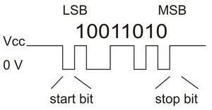
Thanks for posting that oscilloscope trace. It confirms that the signal on the Wixel’s RX line is inverted, when it should actually be non-inverted. Each byte should look like this:
The MOSFET you choose should be able to turn well when its gate is driven high. This means that its gate threshold voltage ( VGS(th) ) should be significantly lower than 3.3 V. You should also look at the maximum ratings of the MOSFET to make sure to make sure it can handle the conditions you will be putting it in. I don’t expect temperature or power dissipation to be an issue for your application, but it is definitely important to check the voltage ratings.
–David
Hi David,
I had the SN74LS06N which is an hex inverted buffers/drivers with open-collector high voltage outputs. I tried it out without the Wixel, simulating the pull-up resistor and I got what I wanted, and this was the non-inverted signal. Now that I got the signal that I wanted, which it was a non-inverted signal with voltages between 0 and 3.3v I connected to the WIxel in the Rx line but when I did this the signal came all the way down, the good thing is that the Wixel is not showing me anymore the red LED. In the image, I will show you better.

The blue signal is the signal that comes directly from the GPS and the yellow signal is the one that comes out from that buffer/driver pin.
Thanks again David and I really appreciate your help, because I really don’t know what else to do with it. If I don’t get any solution this week I guess I will have to change to XBee Pro.
Have a good day!
This is not the signal you want. Do you see how the voltage is going low between the bytes? Please carefully compare your oscilliscope trace with the diagram I posted in my last post where the voltage is high between bytes. Just comparing the yellow and blue traces in your last post, it looks like you didn’t succeed in inverting the signal.
Also, the voltage levels of the yellow signal look bad: it looks like the signal goes between -0.45 V and .06 V, instead of the desired 0 to 3.3 V.
–David
The signal I meant was the one that I tried with a pull-up resistor, which simulated the resistor inside the Wixel. I don’t know why the signal becomes like in the image once I connect it to the WIxel.
Could you post a picture a of the signal that looks good, with the Wixel disconnected, so I can check it? What is the resistance of your pull-up resistor?
Something in your circuit must be very wrong because you are getting a negative voltage on the Wixel’s RX line. Could you post your complete circuit diagram so we can check it? How are you connecting the oscilloscope to the circuit?
–David
Hi David,
I’m writing you to thank you! You really helped me a lot with this project. I appreciate your help and I also wanted to tell you that everything is working as I needed to. If you need anything from me, about this project, just tell me and I will give you the information. I’m going to make a diagram of how I did it, so if you want I can post it here.
Thanks again. I appreciate it!
Have a good day,
Andres Gonzalez
I’m glad things are working for you now! Yes, it would be nice to see your circuit diagram.
–David
