This morning I was doing some testing for the LSM303D acceleration sensor calibration. I had the board fixed to a wooden block with a 2x7mm screw and the wooden block was fixed to a small camera tripod that can be adjusted to any angle.
I had to stop the tests for several hours as we had some guests come over.
When I returned to my testing I was perplexed because the compass display was completely out of whack even when I removed the board from the test fixture. Especially when the Z-axis was horizontal I could not get any meaningful heading output.
After some head scratching I came to the conclusion that something had to be magnetized somewhere. The small screw seemed to stick to my tools, so obviously it had been magnetized at some point. The next test was to try a magnet on the sensor board and sure enough it stuck like a fly in a flypaper. Turns out that the SMD capacitors are nickel plated and it seems the screw had magnetized at least some of them enough to completely mess up the magnetometer. The next phase is to figure out a way to demagnetize the board.
I know there are special non magnetic capacitors available so maybe this is something to consider for the future revisions of the circuit board.
Edit:
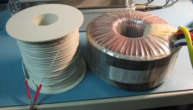
I made a makeshift demagnetizer out of a 70s vintage hifi amplifier, a spool of electric wire and a signal generator. I could only get about 25W out of the setup and could not get every last bit of magnetism out of the board but the improvement was huge. So much so that I eased up heading filtering on my compass board and now have a very decent behaviour when the compass is tilted. This with just an offset calibration.
I suspect it’s the few resistors and two or three capacitors that are closest to the chip that are giving most of the trouble.
We have not heard about this happening before, but I am glad you were able to get the board working again. Can you tell us more about how you made and used the demagnetizer?
I managed to salvage a suitable mains transformer to power my demagnetizing coil. The job turned out to be too much for the poor old hifi amplifier.
The transformer can push a peak amplitude of around 30V into the coil and with that the magnetic flux density in the empty core should be a bit more than 300 Gauss. That should be enough for small objects.
I did some tests by wrapping a coil around some of my various size screwdrivers and monitoring the waveform with an oscilloscope. With the smaller screwdrivers the waveform was clearly distorted, a good sign of a saturated core. For the bigger tools a bit more oomph would be needed.
The actual process is that the object to be demagnetized is brought to the center of the coil, held there for a few seconds in the high intensity magnetic field where the magnetic dipoles in the material turn with the alternating magnetic field. Then the object is slowly moved away axially from the magnet to a distance of maybe one meter. The slow removal causes the magnetic dipoles in the material to freeze in random orientations effectively cancelling each other out so there will be very little external magnetic field left.
Tools can be checked with a compass or iron filings if the process was a success or if it needs to be repeated.
For the LSM303D a new round of magnetic offset calibration is needed. The min and max values should be relatively symmetric in the absence of any disturbing permanent magnetism.
Hello Anthony,
I’m not using any screws, just the connector pins to hold the board. It really is the nickel plating used on the components and connectors that is throwing things off.
My solution was to get a tape recorder head demagnetizer from Ebay and treat the board and the parts nearby with it.
Of course with a clever calibration algorithm all this could be compensated in software (like it’s being done in cell phones and tablets). Without doing the hoops of rotating my phone in the figure 8 pattern, it’s compass can’t tell the east from the west. Should probably try the demagnetizer on it as well but as it is not entirely risk free because of the high intensity magnetic fields I haven’t done it yet.
Jorma
I just got three of GY-89 modules (containing LSM303D) from Aliexpress.
The Y-axis accelerometer had a huge offset. I had to change from ±2g to ±4g to prevent overflow. I read somewhere that this might have been caused by stresses on the chip or heat damage from soldering.
All Magnetic axis were only giving small changes. Demagnetizing the module with a tape demagnetizer solved the problem.
Edit: That demagnetizing only worked for one of the three GY-89 modules, the other two have serious problems. I even unsoldered all parts except the LSM303D, and the problem persists with the Z axis mag having a limited range, and only producing negative values unlike the other X and Y axis having about ±3000 on the ±2gauss range.
If there are any visible soldering issues (cold joints, excess solder, or physical strain on the chip), reflow the board or carefully inspect it under a microscope. Also, perform a full 3D calibration on the LSM303D magnetometer. This involves rotating the module in all directions to gather offset and scaling data for each axis.
No such visible problems exist on the GY-89 module boards that I received from Aliexpress.
From what I understand, 3D calibration is a software procedure done outside the chip, and simply stores values on your computer/Arduino etc. The factory calibration of the chip cannot be done by the end user, correct?
In my case, the offsets on the accelerometer and compass values indicates that improper (or non-existent) factory calibration was performed outside my control.
I am starting to get an idea why the LSM303D chip was obsoleted. I have many chips on the Pololu modules that exhibit locked accelerometer readings and the 1kohm resistor loaded power supply “fix” did not work.