I have 5V power connected to the VIN pin. (I doubled check the incoming 5V with a multimeter. It’s steady.).
The voltage regulator’s VIN pin is soldered to the SHDN pin as per the documentation.
Ground is connected to the GND pin.
When I measure the VOUT pin on the voltage regulator with a multimeter, it is jumping all over the place, from about 1.6V to about 3.5V. When I turn the little potentiometer, it seems like it might be changing the VOUT (not sure), but VOUT is still bouncing all over the place.
My first guess would be that there is too much load on the regulator and it is cutting out. Do you have anything attached to its output? If the output still jumps around when nothing is connected, could you post pictures of your setup and tell me more about your power supply?
I have a large capacity 7.4V LI-ON battery (fully charged to 8.2V) connected to my custom PCB. This incoming voltage is stepped down to 5V using a Pololu 5V regulator. Very light load. The 5V output looks steady and strong on multimeter. The 5V is then feeding into the adjustable Voltage Regulator, which I want to set to 3.7V. But even with no load, it is bouncing all over the place. I’ve tried adjusting it in both directions but it doesn’t appear to help. Could it be that the 5V is too close to the 3.7V for this Voltage Regulator to handle?
I would not expect the regulator to behave like that if there is just an issue with the dropout voltage. As well as posting pictures, could you try powering the regulator directly from your battery and seeing if that makes a difference?
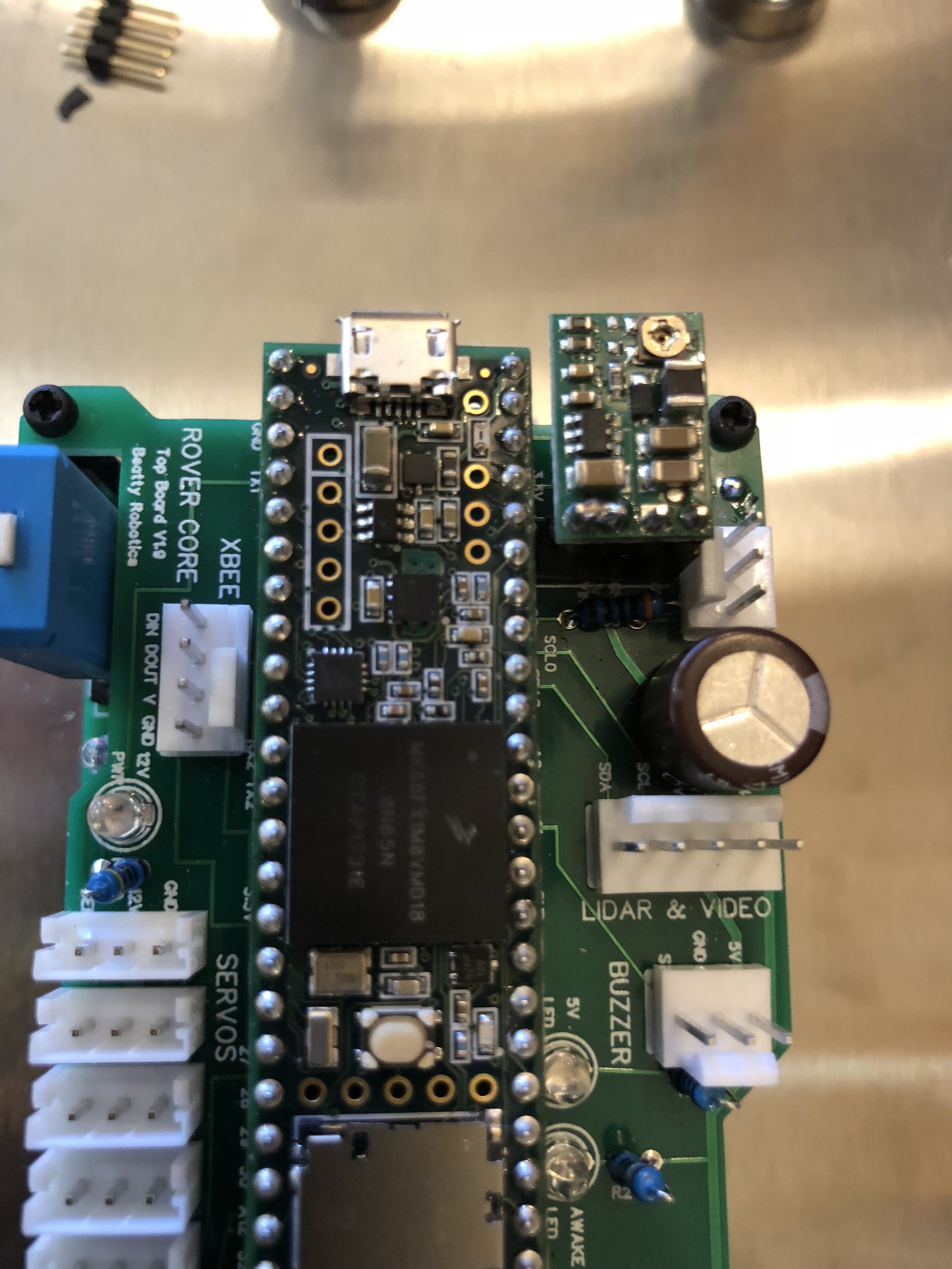
I’m afraid the photo might not show you much.
This is a custom PCB. The VR is plugged into a standard Dupont header.
It has a good 5V and ground connection (measured on multimeter)
Also note that VIN is soldered to SHDN pin on the top of the board.
The VOUT and GND from the VR goes out to the 3-pin connector you see to the right of the VR.
It’s a straightforward situation with no resistors, capacitors, or other elements involved.
I guess I’ll need to pull the VR and wire it up separately to test its behavior independent of the PCB.
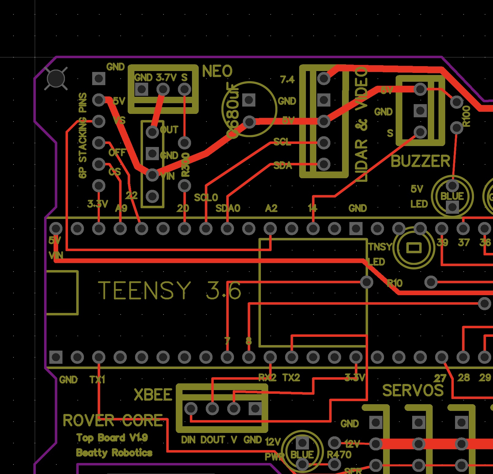
I’ve been thinking more about the problem and looking more closely at the PCB schematic.
Note how the 5V power rail is going to the VIN of the voltage regulator.
Farther on down the 5V power rail, toward the next connector, there is a 680uF capacitor.
Could that be causing the fluctuating up and down on the Voltage Regulator?
It doesn’t seem likely. When I measure the VIN pin on the voltage regulator, I’m seeing 5V steady. It doesn’t appear to be fluctuating. Only the VOUT is fluctuating.
By the way, all the rectangular GND pins are connected to a grounded copper area in the board.
I removed the voltage regulator from the PCB and wired it up in a simplified workbench situation.
I connected the VIN and GND to a workbench power supply and set it to 5V.
I connected VOUT and GND to a multimeter.
It fluctuated up and down just like before.
I then increased the VIN from 5V to 7.4V and then 8.4V.
At 7.4V and 8.4V the VOUT stabilized.
I then used the potentiometer to set the VOUT to my desired 3.7V.
I then lowered the VIN back to 5V.
It started fluctuating just like before.
So, it appears that this model of voltage regulator, or at least the one I have, is not capable of regulating 5V down to 3.7V. It appears that it needs a higher VIN to have a VOUT of 3.7V.
Do you think this model of VR is not capable of what I’m trying to do (going from 5V to 3.7V)? Or do you think I have a bad specimen?
In my case, I have some options. For example, on my PCB, I have a 7.4V power trace near by, so I can manually solder a jumper wire over to VIN on the underside of the PCB. On the next iteration of the PCB, I can make sure to supply 7.4V instead of 5V to the Voltage Regulator. Or should I try replacing the voltage regulator altogether?
I found a second 2103 Voltage Regulator in my stock. It behaved just like the first one. So, it doesn’t look like the first one was defective. It looks like it just won’t do what I was asking it to do. So, I will provide it 7.4V instead of 5V.
It seems I was mistaken. I tested one of those regulators here as well, and it looks like the behavior you are seeing is due to the dropout voltage. With 5V in, the highest steady output voltage I was able to get was about 3.3V.
You can see the dropout voltage curves for that family of regulators at the bottom of the product pages for the fixed output voltage units. For 3.3V out they have around a 1.5V of dropout with very light loads. In your case, it does seem best to just power the regulator from your 7.4V battery. If you want to convert from 5V to 3.7V in the future, you might consider using our S9V11MA step-up/step-down regulator. Then you won’t have to worry about the dropout.