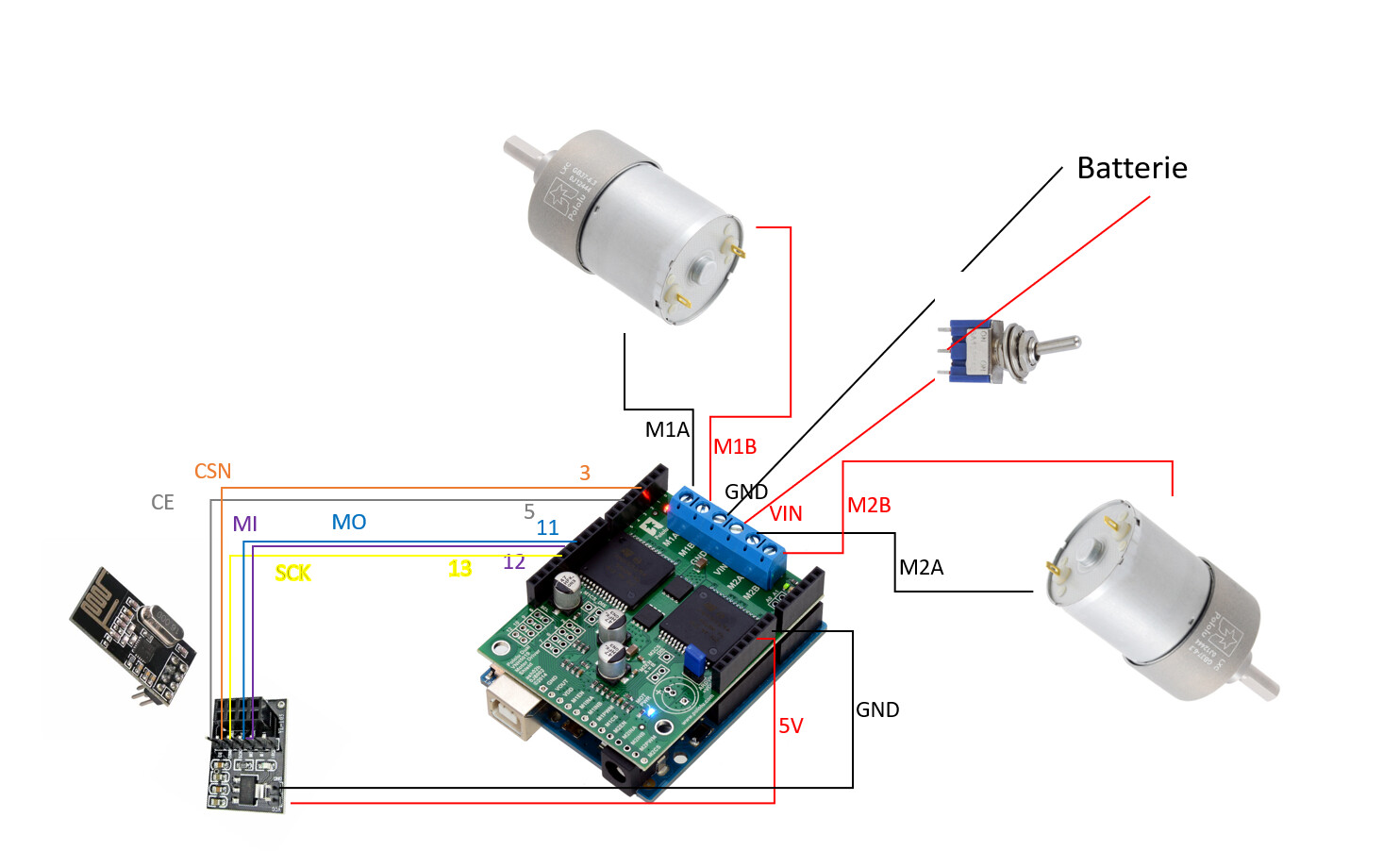
I’m using a Pololu Dual VNH5019 Motor Driver Shield connected to an arduino Uno. On this, i have 2 Pololu motors connected and 1 NRFL2401 module for a remote controller.
I want to control also a Servomotor but it seems that i don’t have any PWM PIN available anymore
Is there a solution ?
This section from our Zumo shield guide on controlling a servo with an Arduino Uno has code for using Timer 2, which should not interfere with the VNH5019 shield.
Well, this is not exactly my issue
The shield is using by default some PINS.
So i only have available the PINS 3, 5, 11 and 13, but all of them are used for the NRFL2401 !
I have no more PWM PIN to use for the servo
Is there any clue ?
I tried with the link @Claire provide above.
And i can move the servo with it by using the PIN 6. But in the code, i just can move servo OR motors depending on which initialization is done in last between the “motor init” and the “servo init”.
I guess because the PIN 6 is used for both
Can you please to find a way to make working both servo and motors with the shield and the NRF24L01 ? Or it’s just impossible ?
#include "DualVNH5019MotorShield.h"

#include <SPI.h>
#include <nRF24L01.h>
#include <RF24.h>


DualVNH5019MotorShield md; // declaration pour le shield Pololu

// pour Servo //////////////////////
#define SERVO_PIN 6
// This is the time since the last rising edge in units of 0.5us.
uint16_t volatile servoTime = 0;
// This is the pulse width we want in units of 0.5us.
uint16_t volatile servoHighTime = 3000;
// This is true if the servo pin is currently high.
boolean volatile servoHigh = false;
int mapServo = 0;
////////////////////// pour Servo /

void stopIfFault()
{
  if (md.getM1Fault())
  {
    Serial.println("M1 fault");
    while(1);
  }
  if (md.getM2Fault())
  {
    Serial.println("M2 fault");
    while(1);
  }
}

RF24 radio(5, 3); // CE, CSN du module wireless

const byte address[6] = "00001"; // Canal de communication entre les modules wireless

struct Pack
{
  int vX;
  int vY;
  int SW_state;
  int But_state;
  int vX2;
  int vY2;
  int SW_state2;
  int But_state2;
}pack;

int mapX = 0;

void setup()
{
  Serial.begin(115200);
  Serial.println("Dual VNH5019 Motor Shield");

  //md.init(); // work only if servoInit() is commented
  servoInit(); // work only if md.init() is commented

  // initialisation pour le module Wireless
  radio.begin();
  radio.openReadingPipe(0, address);
  radio.setPALevel(RF24_PA_MIN);

}

void loop()
{
  radio.startListening();

while  (radio.available()) {
  radio.read( &pack, sizeof(pack) );
  mapX = map(pack.vX, 0, 1023, -200, 200);
  mapServo = map(pack.vY2, 0, 1023, 1000, 2000);

  servoSetPosition(mapServo);
  delay(20);

//if ((mapX > 20) || (mapX < -20)) {
//  stopIfFault();
//  md.setSpeeds(-mapX,-mapX); // on inverse car le joystick est a l'envers
//  }
//  else {  ////////////////////////////////////////////////////////////////////////////// a l'arret
//    stopIfFault();
//    md.setSpeeds(0,0);
//  }
}

  Serial.print("X droite: ");
  Serial.print(pack.vX);
  Serial.print(" | Y droite: ");
  Serial.print(pack.vY);
  Serial.print(" | Bouton droite: ");
  Serial.print(pack.SW_state);
  Serial.print(" | Push droite: ");
  Serial.print(pack.But_state);

  Serial.print(" |||| ");
  Serial.print(" X gauche: ");
  Serial.print(pack.vX2);
  Serial.print(" | Y gauche: ");
  Serial.print(pack.vY2);
  Serial.print(" | Bouton gauche: ");
  Serial.println(pack.SW_state2);
  Serial.print(" | Push gauche: ");
  Serial.print(pack.But_state2);

  //Serial.print("X: ");
  //Serial.print(mapX);
  //Serial.print(" | Y: ");
  //Serial.print(mapY);
  //Serial.print(" | Bouton: ");
  //Serial.println(pack.SW_state);
}

// pour Servo //////////////////////
  // This ISR runs after Timer 2 reaches OCR2A and resets.
// In this ISR, we set OCR2A in order to schedule when the next
// interrupt will happen.
// Generally we will set OCR2A to 255 so that we have an
// interrupt every 128 us, but the first two interrupt intervals
// after the rising edge will be smaller so we can achieve
// the desired pulse width.
ISR(TIMER2_COMPA_vect)
{
  // The time that passed since the last interrupt is OCR2A + 1
  // because the timer value will equal OCR2A before going to 0.
  servoTime += OCR2A + 1;

  static uint16_t highTimeCopy = 3000;
  static uint8_t interruptCount = 0;

  if(servoHigh)
  {
    if(++interruptCount == 2)
    {
      OCR2A = 255;
    }

    // The servo pin is currently high.
    // Check to see if is time for a falling edge.
    // Note: We could == instead of >=.
    if(servoTime >= highTimeCopy)
    {
      // The pin has been high enough, so do a falling edge.
      digitalWrite(SERVO_PIN, LOW);
      servoHigh = false;
      interruptCount = 0;
    }
  }
  else
  {
    // The servo pin is currently low.

    if(servoTime >= 40000)
    {
      // We've hit the end of the period (20 ms),
      // so do a rising edge.
      highTimeCopy = servoHighTime;
      digitalWrite(SERVO_PIN, HIGH);
      servoHigh = true;
      servoTime = 0;
      interruptCount = 0;
      OCR2A = ((highTimeCopy % 256) + 256)/2 - 1;
    }
  }
}

void servoInit()
{
  digitalWrite(SERVO_PIN, LOW);
  pinMode(SERVO_PIN, OUTPUT);

  // Turn on CTC mode.  Timer 2 will count up to OCR2A, then
  // reset to 0 and cause an interrupt.
  TCCR2A = (1 << WGM21);
  // Set a 1:8 prescaler.  This gives us 0.5us resolution.
  TCCR2B = (1 << CS21);

  // Put the timer in a good default state.
  TCNT2 = 0;
  OCR2A = 255;

  TIMSK2 |= (1 << OCIE2A);  // Enable timer compare interrupt.
  sei();   // Enable interrupts.
}

void servoSetPosition(uint16_t highTimeMicroseconds)
{
  TIMSK2 &= ~(1 << OCIE2A); // disable timer compare interrupt
  servoHighTime = highTimeMicroseconds * 2;
  TIMSK2 |= (1 << OCIE2A); // enable timer compare interrupt
}
  ////////////////////// pour Servo /
Pin 6 is used by the VNH5019 library by default for EN1DIAG. You can see all the default pins the library uses in its DualVNH5019MotorShield.cpp file. You can move the servo pin to another unused pin by changing line 17 of the example code to:
#define SERVO_PIN A2
A2 can be replaced with any pin number that is convenient.