Im new to electronics.
Im trying to make a pololu 37D 100:1 motor work being controlled with my pi4b via VNH5019.
So far unsuccessfully.
My wiring is right (I think) OUT A abd OUT B are connected to the motor. VIN and GND being powered by a 2S lipo 80C 2200mAh.
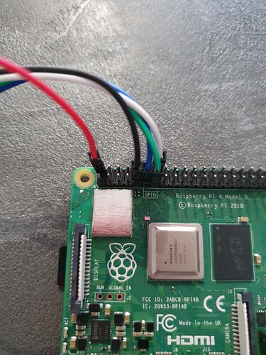
On the other side VDD is on pin 2 (5V).
INa and INb are in pins 11 and 13,
PWM in 12,
GND in 9.
My code uses RPi.GPIO library which it might be the issue?
When I run my python code, nothing happens. The code, however, runs without errors.
Hello.
Could you clarify if you are using the VNH5019 Motor Driver Carrier or the Dual VNH5019 Motor Driver Shield?
We do not have a Raspberry Pi library specifically for the VNH5019, but you should be able to use them together. Could you post some pictures of your setup that show all of your connections as well as close-up pictures of both sides of your VNH5019 board? Also, could you post the simplest but complete version of your code that demonstrates the problem?
Brandon
Thank you for your quick reply @BrandonM
I use the VNH5019 Motor Driver Carrier (not dual)
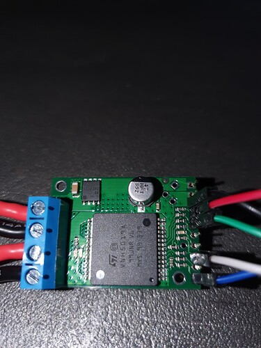
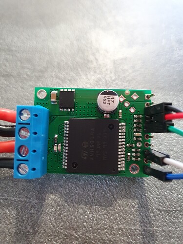
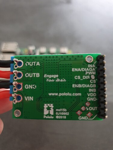
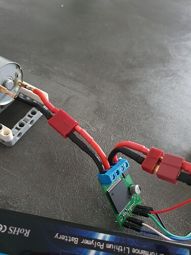
These are my photos:
A very simple code test (my console will print the ‘print’ statements without error, but the motor won’t move and the Driver doesn’t even get warm. I have tried connecting the battery to the motor directly and it spins fine:
import RPi.GPIO as GPIO
import time

print("program started")

# Set the GPIO mode
GPIO.setmode(GPIO.BCM)

# Define GPIO pins for motor control
INa = 17  # GPIO17 (Pin 11)
INb = 27  # GPIO27 (Pin 13)
PWM = 18  # GPIO18 (Pin 12)

# Set up the GPIO pins
GPIO.setup(INa, GPIO.OUT)
GPIO.setup(INb, GPIO.OUT)
GPIO.setup(PWM, GPIO.OUT)

# Set up PWM
pwm = GPIO.PWM(PWM, 1000)  # Set PWM frequency to 1kHz
pwm.start(100)  # Start PWM at 100% duty cycle (full speed)

try:
    # Set motor direction
    GPIO.output(INa, GPIO.HIGH)  # Forward
    GPIO.output(INb, GPIO.LOW)

    # Run the motor for 5 seconds
    time.sleep(5)

finally:
    # Stop the motor and clean up
    pwm.stop()
    GPIO.cleanup()

print("program finished")
Thank you for the pictures. It looks like you have not soldered any of your connections. Before trying to troubleshoot anything else, you will need to solder your connections to ensure a solid and reliable electrical connection. This includes the screw terminal blocks on the power and motor output side of the board, as well as the 0.1" header pins on the logic side of the board. Please note that the short side of the header pins should be inserted into the board and soldered from the other side (similarly to how they are on the Raspberry Pi), and the terminal block pins should be soldered to the large holes.
If you are new to soldering, I recommend reading through Adafruit’s Guide to Excellent Soldering. You might also find this video about installing terminal blocks useful.
Brandon
Thank you @BrandonM . Yes, I’m new to all of these. I didn’t want to solder before knowing that my connections were correct. I think I understand and will follow your instructions. The logic side the one where the holes are described. Right?
If you solder the provided screw terminal blocks and 0.1" male headers to the board, then none of the external connections you make to those need to be permanent.
Yes, the logic pins I was referring to are the ones along the opposite edge of the board from the motor and power connections.
Brandon

