Hello,
I’d bought the VNH3SP30 H Bridge Motor Driver from pololu and prepared my own board for motor driving. While the board works perfectly for small motors, when I shift to larger motors, the motors just don’t run.
I’m giving the logical inputs using an Atmega series controller, such that if I want the motor to move ahead, I give 5 volt at Input A and GND at Input B. However with a large motor at the output terminals, the input pins are being pulled to ground for some odd reason. This means that both input B and A are registering around zero or slightly negative voltage with respect to ground.
However, I tried giving the same 5 volt supply using a power supply, and it works perfectly. My motors are running brilliantly, but quite obviously, I need to provide this power from my Atmega on a moving robot, and not from a power supply. Any clues on why its going into such a shutdown? There is no heating happening, no motor movement at all.
(Specifications: Motor Resistance at stall : 3 ohm, approx; Voltage across motor terminals: 13 Volts. Atmega series controller works at 5 volt logic high and 0 volt GND)
Could someone help here with their own schematics/any particular reasoning to why the inputs are being pulled low…
by voltage across motor terminals, i meant the supply voltage on which the motors r being driven.
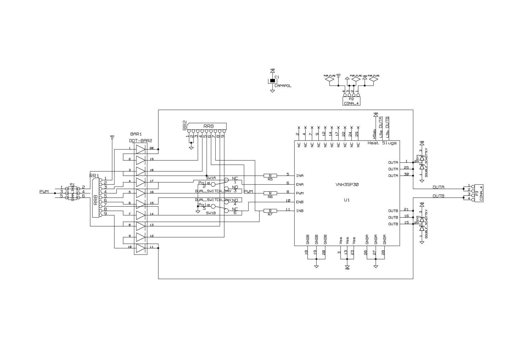
i have attached an image of the schematic made in Kicad.
also, the driver isn’t reporting any problem on the diagnostic lines.
my problem is that VNH pulls its i/o lines to -0.12V during the reverse battery condition, which is an expected condition according to the driver’s specs.this is inspite of the huge 2amp schottkey diodes placed.
this is unacceptable to my atmega’s o/p pin, inspite of the current limiting resistors.
all resistances in the circuit are 1k.
due to this problem i cant control the motor from my atmega, but if i connect regulated 5v, 5v & 0v lines at the connector instead of atmega’s pins , the big motors run properly.
[quote=“nevada”]this is unacceptable to my atmega’s o/p pin, inspite of the current limiting resistors.
all resistances in the circuit are 1k.[/quote]
What makes you say that this is unacceptable to your AVR? The AVRs I’ve used so far can all tolerate as low as -0.5V on their I/O lines according to the electrical characteristics sections of their datasheets.
I’m not following what you’re trying to do with all the extra diodes. The schematic is pretty hard to follow, so you might want to clean it up some if you want others to understand what you’re doing from it. For instance, if I look at the “PWM” input to the VNH3SP30, it looks like it goes through some resistor and then to the INA line; that seems like a strange thing to do and something you should call out more if it’s intentional. The wires crossing the parts make everything a mess, and you have dots on some 3-way (“T”) connections and not on others.
Also, why are you putting reversed power to the chip, and what are you expecting to accomplish?
i wish to apologize for the ‘reverse battery condition’ terminology used. that is not what i meant.
the actual problem i am facing is the flyback effect of inductive (motor) load which is generating the negative emf of -0.12v on the input line of the driver (which is then being forwarded to my atmega output pin).
the point mentioned of absolute ratings of atmega applies to the input pins (-0.5v min). however i am getting a reverse voltage on my OUTPUT pin. no information relating to this is given in the electrical characteristics of the muc.
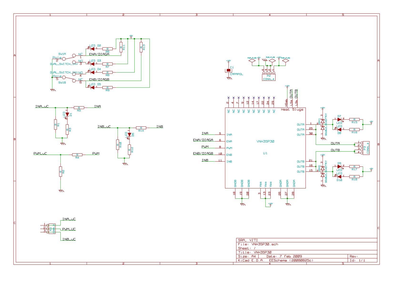
i have cleaned up the schematic to make it more legible. the ‘extra diodes’ mentioned are actually an LED bar used for diagnostics. those have now been replaced by individual LEDs. also pins have been pulled up/low as applicable (again using separate resistors, where formerly resistance strips were used).
the schottkys used in the circuit to deal with flyback are of 2amps.
The resistors in line with your I/O pins should take care of your I/O lines, so the negative voltage shouldn’t be a problem for your microcontroller. However, it’s probably indicative of other problems. Can you post your layout?
i designed the layout in kicad… so jpeg images of individual layers are all i could manage to explain the layout.
also attached are gerber files of this layout.
if u can tell me exactly how u want the layout, then i can try on those lines.
That looks decent. Are you assembling the boards in a way that lets you solder the heat slugs on the bottom of the chip?
How are you measuring the various signals? It would be good to look at an oscilloscope to see how various glitches are correlated, and if you can post screen shots from the scope, that would be even better. It would be good to see how hard the input pins are being pulled down since you do have the pull-down resistors and LEDs on the lines, so it is somewhat expected for the lines to normally be low. What happens if the AVR is not in the circuit and you just use something like a 100-ohm resistor to pull the lines high?
instead of giving signals from an AVR or pulling the lines high thru a resistor, i had directly connected ENA,ENB,INA to +5v & INB to 0v & all motors ran perfectly…(i have no idea why)
i had did this (i.e. not using the AVR) on the very day i found the inability to run big motors.
but i need the AVR in my project for motor control
i dont have access to an oscilloscope, but will try…
and about the heat slugs being soldered, i had given properly sized pads in the layout & the components were machine soldered at a professional soldering place, so i assume ther slugs are soldered…i will get a confirmation and report back
That sounds pretty good since that seems to confirm that the H-bridge itself is fine. So, maybe it’s a firmware problem or a problem with the AVR part of the layout.