I am using the VL6180X sensor and it keeps timing out after sometime though I have disabled timeout (setTimeout(0)). I am using the sensor in interleaved mode to get continuous reading (just used the sample code):
The library and example should not report a timeout if you have set the timeout to 0. Are you using the InterleavedContinuous example with no changes other than setTimeout(0)? Have you ever gotten any valid readings from the sensor or have you only seen timeouts? Could you post some pictures of your setup showing your connections?
As for your other questions, I don’t think there is a way to reset the sensor through I2C, although you could make another connection from your Arduino to the GPIO/CE (chip enable) pin and toggle that to reset it. It’s possible that EMI from nearby motor wires could affect the communications; if you have access to an oscilloscope, you could try using that to check for interference.
Thanks for the reply. I have not made any changes other than the timeout set to 0. The code I posted above is void setup() code.
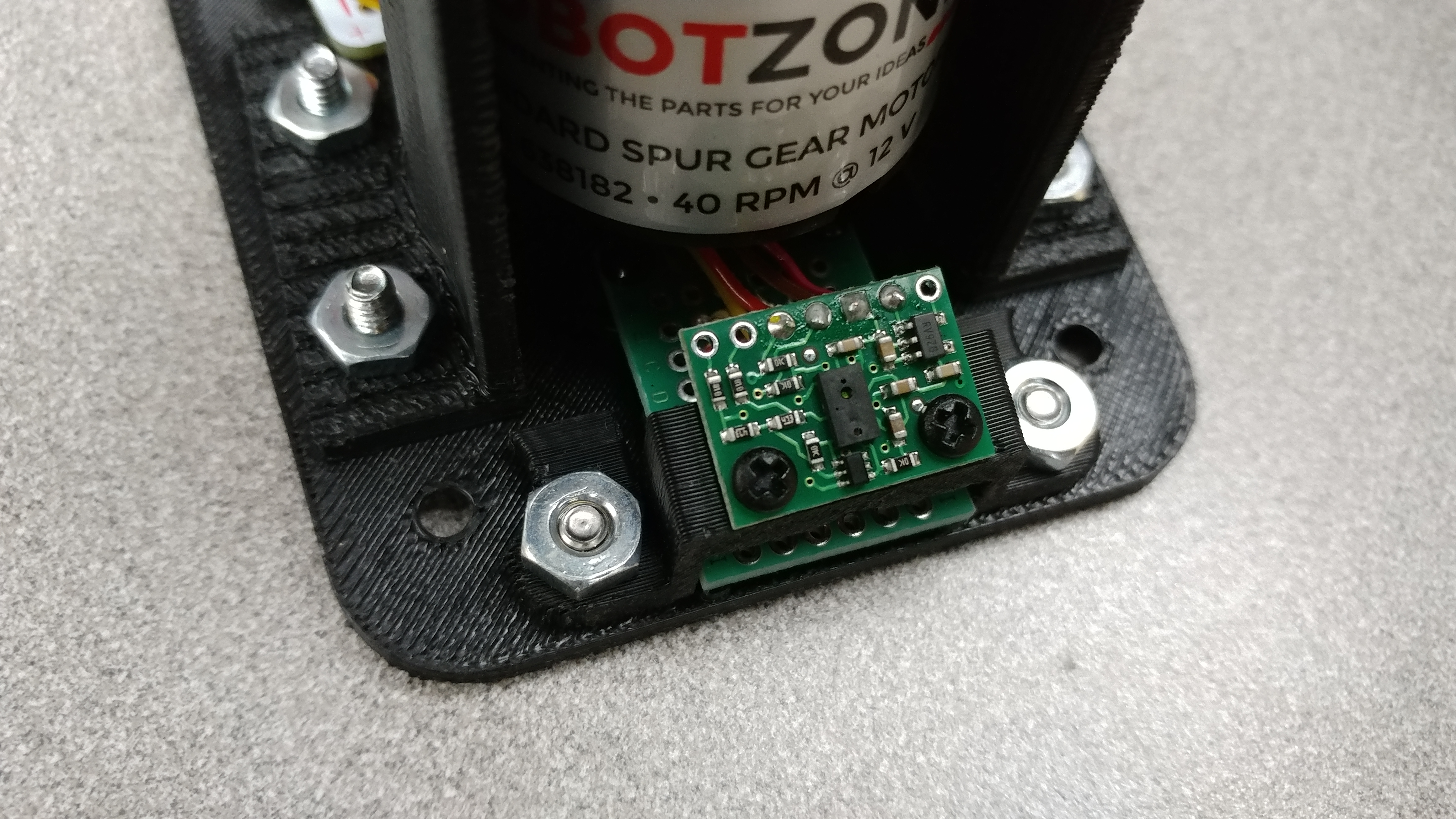
I get valid readings for I think around 5 mins or so, then the sensor times out. I have attached the images with green lines showing the ToF i2c wires and the motor power wires
Could you post a sample of the output you are seeing before and after the sensor times out?
If it is practical for you to disconnect everything other than the VL6180X from your A-Star, could you try that and see if it makes any difference? It would also be helpful if you could post a wiring diagram of your setup, since it is hard to see how everything is connected in the photos. (In particular, how is the VL6180X powered?)
Apologies for the late reply. The relevant wiring diagram would be just a motor and a ToF wire connected to pins on an A-star board. The out put is the output of the example sketch, so again do not know how useful that will be. But, I will try disconnecting the motor and run the ToF and see what happens. Thanks!