Hi,
we are trying to use your vl53l8cx carrier board connected on I2C bus of a NUCLEO L496ZG.
Unlikely other I2C peripherals, we are issuing some bad behavior.
The I2C bus is dedicated to this board only (no other devices with different address are connected to it)
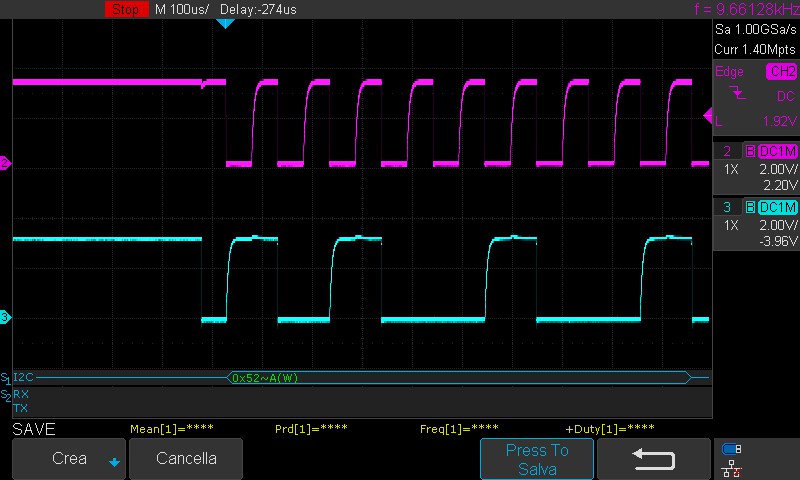
When we start a I2C WRITE to device, it HANGS immediatly and causes drop of voltage on SCL and SDA lines.
If we disconnect the device from bus, the lines are driven correctly.
Please see attached pictures
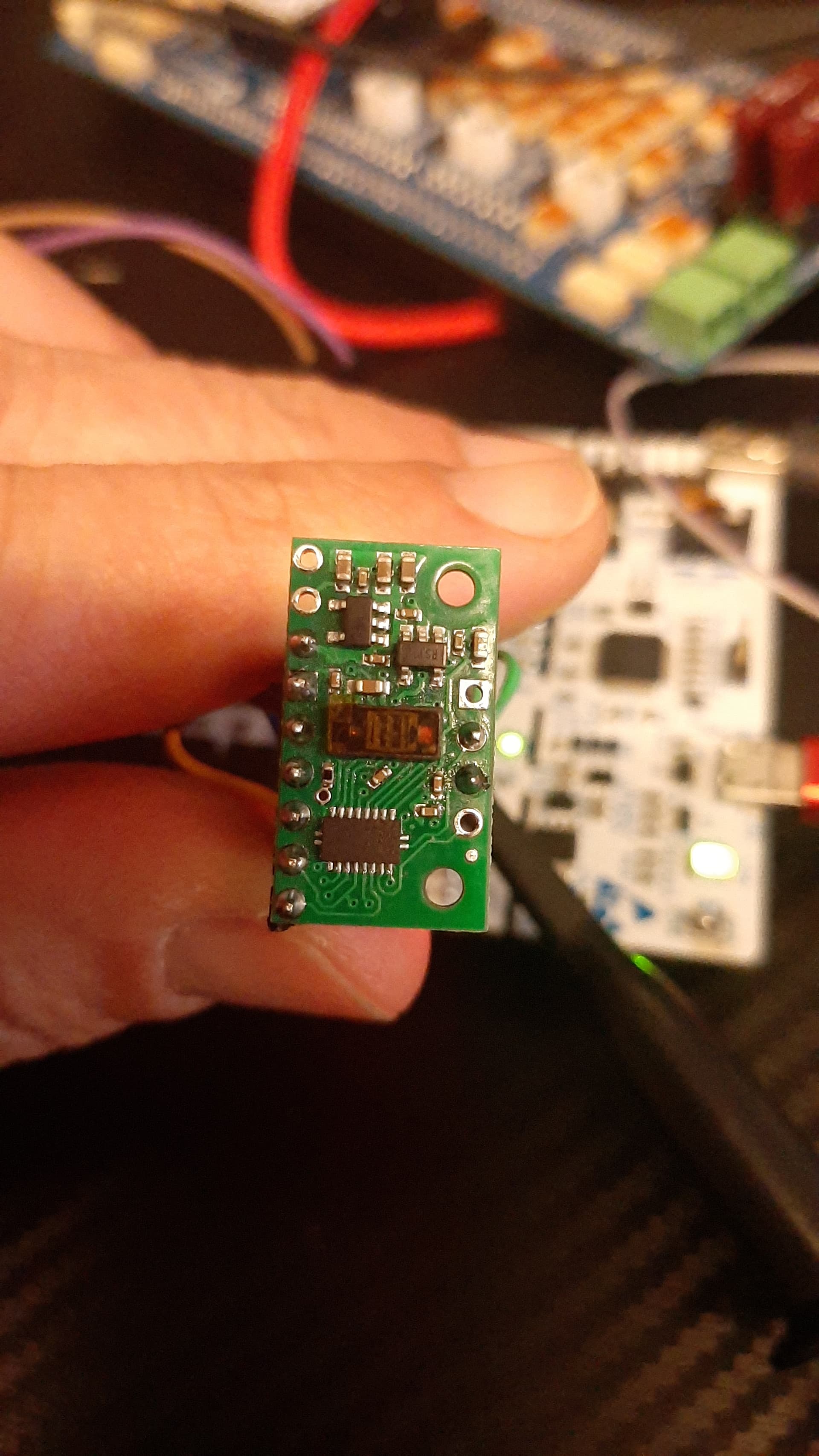
Can you post the code you are using along with some pictures that show all of your physical connections, including close-ups showing both sides of the VL53L8CX carrier?
One thing you might try right away is using shorter wires. As we note on the product page, the level shifter on this board is more sensitive to external loads than the circuit we typically use, so we recommend taking extra care to keep connected communication wires short (ideally under 3 inches or 8 cm). How long are the ones you are using?
It’s not very easy to check your connections from those pictures, so could you list what pins each wire is connected to (on both the Nucleo and the VL53L8CX board)?
For I2C communication, the SPI/I2C pin should be driven or tied low (connected to GND), and LP should be driven or tied high (or you can leave it disconnected for now since it’s pulled up by the board). Can you confirm that is how you have those two pins set up?
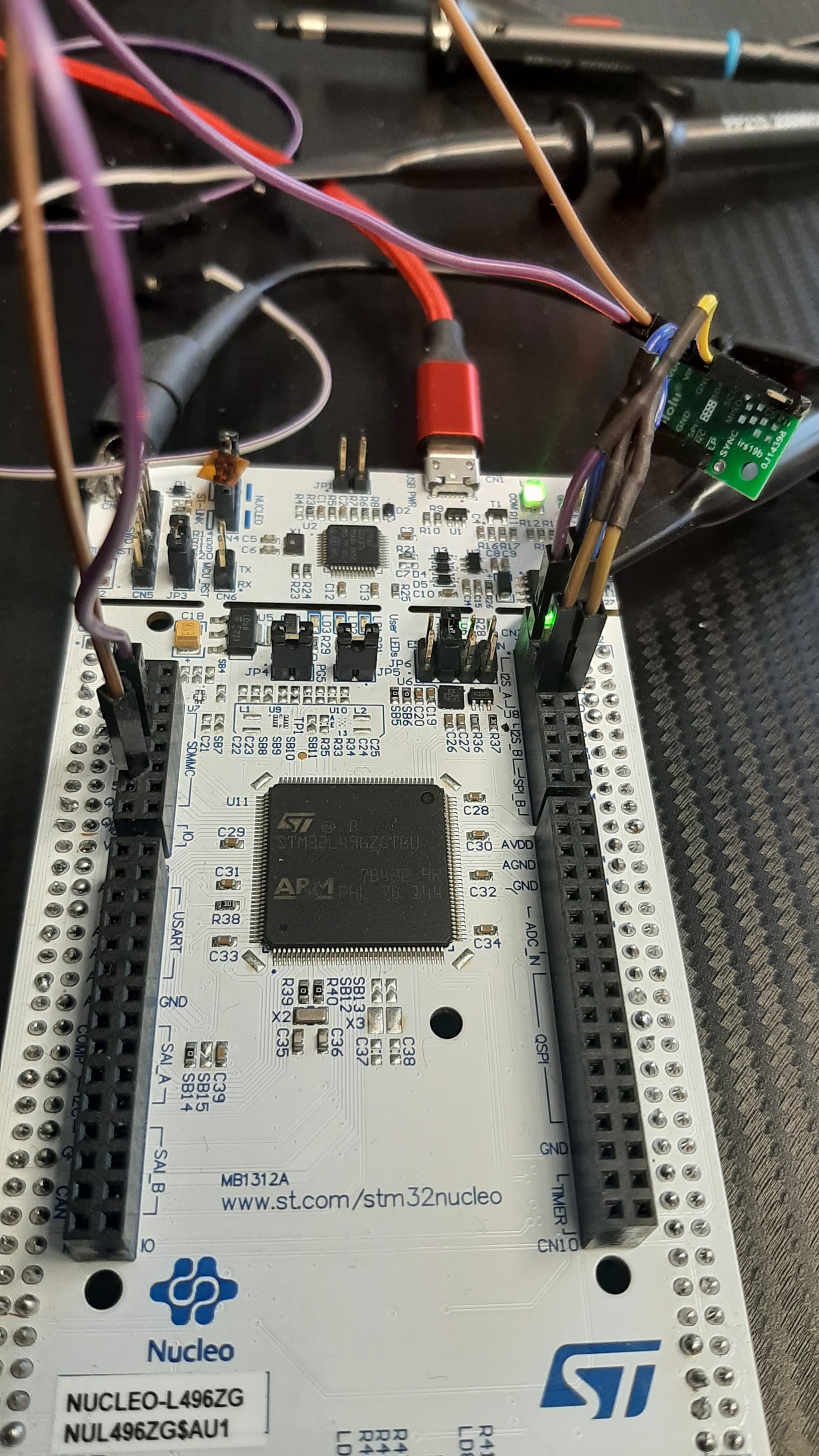
Hi Kevin, you’re right: the pics are a mess, but the shorter the connectors, the more difficult is to “make space”. So I’ll resume connections (see details in attached pics):
VIN connected to V3.3 on connector C8
GND connected to GND on connector C8
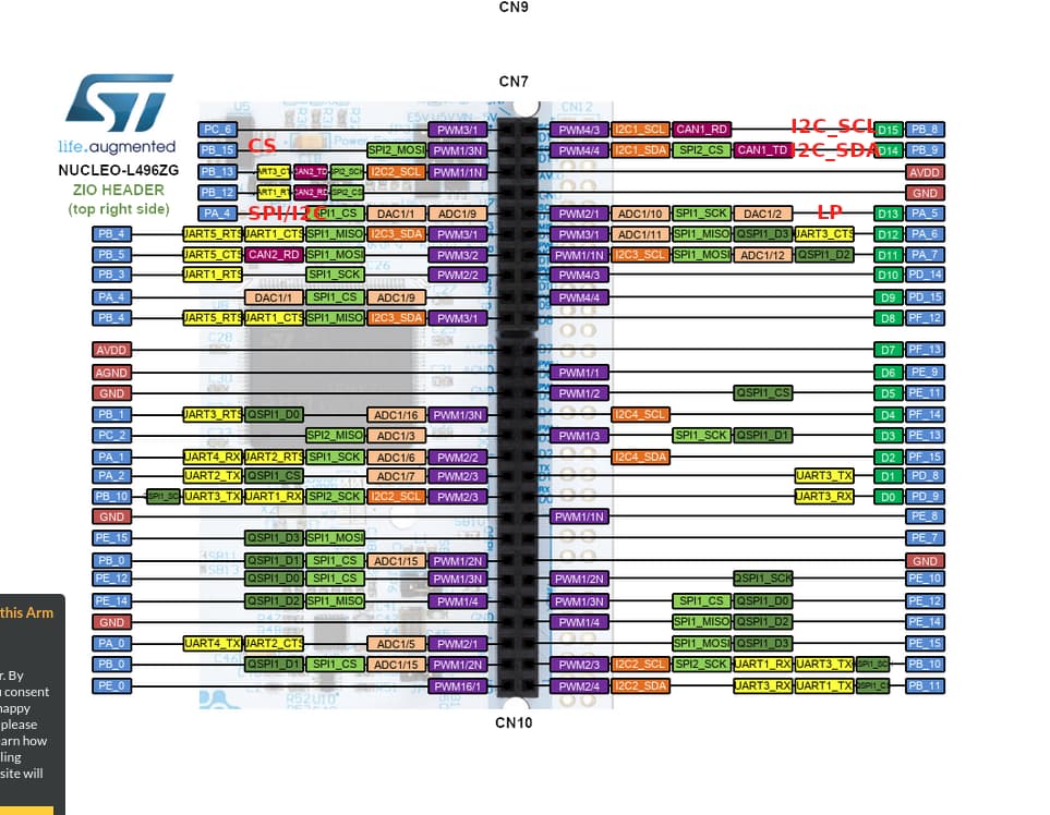
SCL connected to PB_8 (I2C_SCL) on connector C7
SDA connected to PB_9 (I2C_SDA) on connector C7
LP connected to PA_5 (GPIO_OUT) on connector C7 (driven HIGH)
SPI/I2C connected to PA_4 (GPIO_OUT) on connector C7 (driven LOW)
CS connected to PB_15 (GPIO_OUT) on connector C7 (driven LOW)
actually at startup we perform a RESET sequence on PA_4 (LOW-HIG-LOW), in order to reset I2C interface, as reported on datasheet.
Follows initialization code sequence
Since we are in testing phase, could you suggest us other similar devices? We have to detect some object’ positioning/presence (within 20-30 cm)
I saw there are vl53l7 and vl53l5…
Your connections and initialization seem okay to me. Have you been able to communicate with other I2C devices successfully with that Nucleo board?
I am not familiar with the Nucleo L496ZG, but if it is compatible with Arduino code, you could try the STM32duino VL53L8CX library and its examples to see if they work any better for you.
As for comparable sensors, the VL53L5CX and VL53L7CX are the most similar to the VL53L8CX; they differ from each other mainly in their field of view. You might find the comparison table on our ST ToF sensor carrier category page helpful. It’s possible your issue is being caused by the level shifter on our VL53L8CX carrier, which is more sensitive to external loads than the circuit we use on most of our other boards (although your setup doesn’t seem like it should be problematic), so trying a different sensor board could help determine if that’s the case.
Hi Kevin,
we changed sensor’s board and switched to vl53l5cx. Now the I2C communication is working well, and driver can correctly initialize. The problem now is in polling loop:
the function vl53l5cx_check_data_ready set always flag isReady to zero, even if communication occurs correctly (I suppose received data are not as expected).
A probe on INT pin shows it is raised.
Here the loop code:
void vl53l5_loop()
{
	/* Use polling function to know when a new measurement is ready.
	 * Another way can be to wait for HW interrupt raised on PIN A3
	 * (GPIO 1) when a new measurement is ready */

	Status = vl53l5cx_check_data_ready(&Dev, &isReady);

	if(isReady)
	{
		vl53l5cx_get_ranging_data(&Dev, &Results);

		/* As the sensor is set in 4x4 mode by default, we have a total
		 * of 16 zones to print. For this example, only the data of first zone are
		 * print */
		printf("Print data no : %3u\n", Dev.streamcount);
		for(i = 0; i < 16; i++)
		{
			printf("Zone : %3d, Status : %3u, Distance : %4d mm\n",
					i,
					Results.target_status[VL53L5CX_NB_TARGET_PER_ZONE*i],
					Results.distance_mm[VL53L5CX_NB_TARGET_PER_ZONE*i]);
		}
		printf("\n");
	}

	/* Wait a few ms to avoid too high polling (function in platform
	 * file, not in API) */
	VL53L5CX_WaitMs(&(Dev.platform), 5);
}
Now I’ll try to connect a serial to collect printf output, in order to have more debug info.
Hi again, Kevin.
The problem is that vl53l5cx_init() fails with status == 1. It means that timeout is exceeded when _vl53l5cx_poll_for_answer is issued. Timeout is set to 2s. I’ve raised to 10s but it still expires.
Any idea about how to unlock this?
Thanks
Enrico
What implementation of the VL53L5CX API are you using, and is your main program an example that you found or one that you wrote yourself? If you wrote it yourself, can you post the full program as an attachment (or a simplified version that demonstrates the issue)? How did you determine that _vl53l5cx_poll_for_answer() is causing the problem (and which instance is it, since that function is called multiple times from vl53l5cx_init())?
Also, can you show some pictures of your new board and setup so that I can check them again?
I’ve downloaded the library from ST download page
I’ve copied the initialization and loop from example1_range_basic.c source file
With STM32 Cube IDE I’ve put a breakpoint in _vl53l5cx_pool_for_answer at line 41 when timeout expires (vl53l5cx_api.c) where timeout error flag is set.
The instance where this happens in vl53l5cx_init is at line 277 when sensor is rebooted after 1st SW reboot sequence.
The I2C communication now seems working, since all read/write commands returns HAL_OK.
I’ll send you some pictures on next post.
I’ve connected VIN to 3.3V, I2C_RST is connected to a gpio driven LOW, while LPn to a gpio driven HIGH.
Hi, I’ve had some improvements, reviewing implementation of Read/Write functions.
Now the _vl53l5cx_pool_for_answer does not lock anymore.
The initialization goest through until the FW flashing, where it returns an error in transmission.
/* Download FW into VL53L5 */
	status |= VL53L5CX_WrByte(&(p_dev->platform), 0x7fff, 0x09);
	status |= VL53L5CX_WrMulti(&(p_dev->platform),0,
		(uint8_t*)&VL53L5CX_FIRMWARE[0],0x8000);
	status |= VL53L5CX_WrByte(&(p_dev->platform), 0x7fff, 0x0a);
	status |= VL53L5CX_WrMulti(&(p_dev->platform),0,
		(uint8_t*)&VL53L5CX_FIRMWARE[0x8000],0x8000);
	status |= VL53L5CX_WrByte(&(p_dev->platform), 0x7fff, 0x0b);
	status |= VL53L5CX_WrMulti(&(p_dev->platform),0,
		(uint8_t*)&VL53L5CX_FIRMWARE[0x10000],0x5000);
	status |= VL53L5CX_WrByte(&(p_dev->platform), 0x7fff, 0x01);
/* Check if FW correctly downloaded */
	status |= VL53L5CX_WrByte(&(p_dev->platform), 0x7fff, 0x02);
	status |= VL53L5CX_WrByte(&(p_dev->platform), 0x03, 0x0D);
	status |= VL53L5CX_WrByte(&(p_dev->platform), 0x7fff, 0x01);
	status |= _vl53l5cx_poll_for_answer(p_dev, 1, 0, 0x21, 0x10, 0x10);
	if(status != (uint8_t)0){
		goto exit;
	}
The 1st write multi returns status!=0 (0xFF) hence initialization fails
Please let me share how platform.c is implemented, since I suspect it fails transmitting huge arrays of data on I2C vl53l5cx_platform.c (3.6 KB)
Hi Kevin, good news!
I could get rid of this: found an existing implementation of platform part for STM, and actually was wrong the implementation. Both WriteMulti and ReadMulti, were not working. Here the correct implementation
Now the sensors initializes and runs correctlry.
Thanks for your support!
Enrico
Interestingly, we see exactly the same problem with the I²C behavior of the VL53L8CX.
We also tried numerous configurations.
Our main goal is to test the sensor first. To do this, we tried a typical, simple sketch that loops through all 127 I²C addresses and waits for confirmation from an I²C slave device. This code structure has been tested and works perfectly. When using other I²C devices, their addresses will be displayed correctly in the serial printout. According to the datasheet, the VL53L8CX should appear as 0x52, which was not the case.
Pin Configuration of the VL53L8CX
We powered the Dev Board with 3.3V on Vin. AVDD is internally set to 3.3V by an internal LDO. Another internal LDO creates a 1.8V supply for the VL53L8CX itself. The communication pins are then shifted to the Vin level using an integrated level shifter. The 3.3V at Vin and AVDD, and the 1.8V at Core/IOVDD, were checked.
The SPI/nI2C pin is set low by a 47k resistor (a direct connection to ground was also tested). The nLP pin is set high. (We also tried toggling something for initialization, or starting low first and then setting it high later, but nothing helped; the behavior remained unchanged.) The SYNC, nCS, and INT pins were left floating at first, and later nCS was also settled to GND via a 47k pulldown resistor. The behavior remained unchanged.
We tried smoothing the power supply with some capacitors and double-checked the breadboard and jumper cable setup.
We tried three different VL53L8CX development boards. (Behavior remained unchanged.)
We tried using different pull-up resistor values for the I²C bus. (Behavior remained unchanged. Other I²C devices thereby always showed up correctly on the bus.)
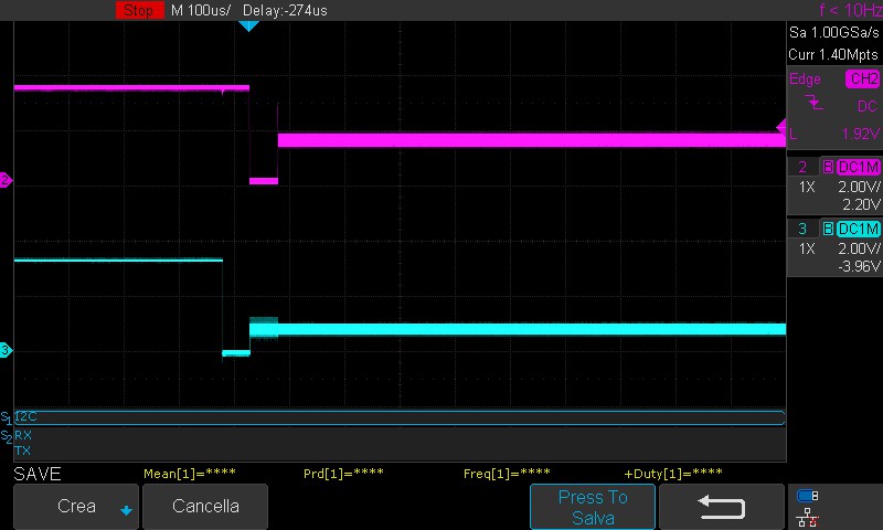
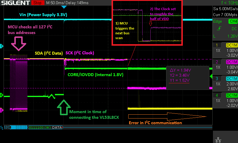
Problem:
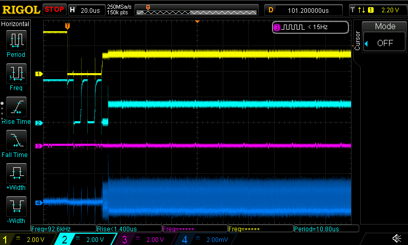
The situation is recorded with the oscilloscope. It is triggered by the raising of the Core/IOVDD level (to 1.8V) while the VL53L8CX is inserted into the board and gains electrical connection to the pins.
The next time the microcontroller scans the bus, the connection runs into a timeout because the clock gets stuck in an undefined state of around 1.5 V. Interestingly, this is roughly half of Vin (3.3V). One device was also tested with logic levels of 5V at Vin and for the I²C lines when pulled high. (This should also be handled by the level shifter.) The behavior remained the same, but the CLK got stuck at around 2.5V, which is also around half of the Vin voltage. The CLK-stuck voltage also remained at this state by fine-tuning the pull-up resistors, which looks as if they are kept active.
Do you have any suggestions on how to address the sensor?
There may be a problem with this particular batch.
It is not clear whether @enrico.bandera had the same problem since they switched to the VL53L5CX before we fully diagnosed the issue, but the behavior you are seeing now looks like it could be caused by the level shifter on our VL53L8CX carrier. The level shifter we use on this board is more sensitive to external loads than the circuit we typically use, so we recommend taking extra care to keep connected communication wires short (ideally under 3 inches or 8 cm) and limit other devices on the same I²C or SPI bus.
Can you tell me what specific microcontroller and power supply you are using with the VL53L8CX as well as if there are any other components in the setup? Can you also post some pictures of your setup that show all of your connections and try testing the board with shorter wires to see if that helps?
With your help, we’re now one step further.
We’ve mainly been using longer cables. With shorter ones the clock is no longer pulled into the undefined state.
The bus is not irritated by the VL53L8CX now, but the sensor does not respond to his address either.
Other I²C bus participants are undisturbed now.
Thank you for that.
In the pictures you can see our breadboard built and some from the oscilloscope screen.
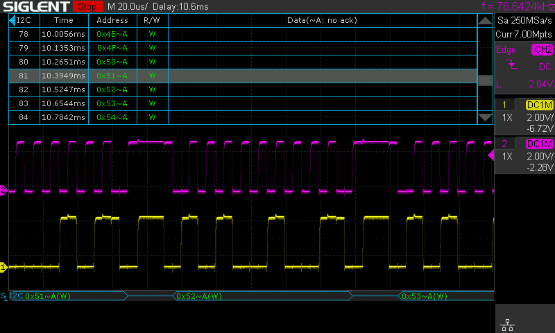
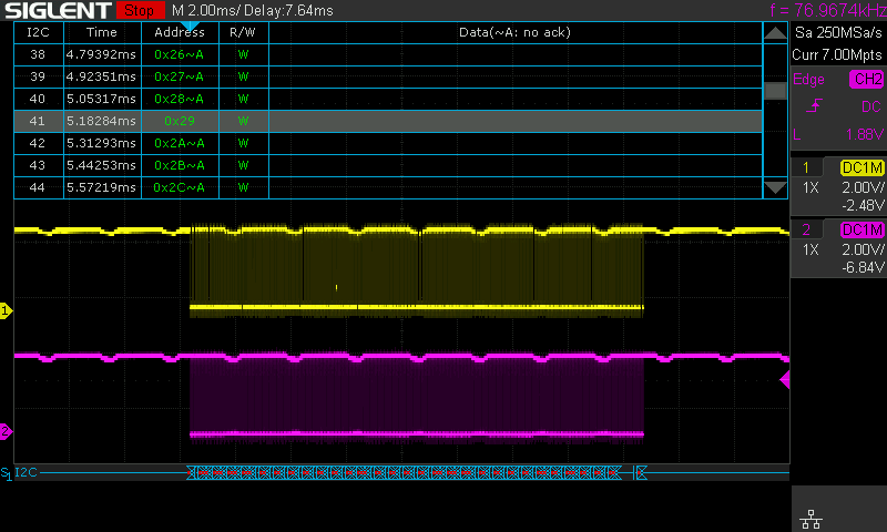
The oscilloscope shows one sensor at 0x29 acknowledge its address. This is also decoded showing not the “~A” symbol by the scope (41 in decoding list).
This sensor is also detected by the Microcontroller.
The VL53L8CX does not react to its default address at 0x52 or any other.
Regarding the MCU, we are currently using a Arduino Nano, which also operates at 3.3V due to its logic high level and the I²C pullups that are also set to 3.3 V.
We are currently using the Arduino’s internal 3.3V LDO as the power supply, but have also tried using an external source.
So the new question is: Why doesn’t the VL53L8CX confirm its address?
I am glad to hear we are making some progress. It looks like you are connecting the SPI/nI2C pin to ground through a resistor, but the level shifter pulls the pin up with the equivalent of about a 4k resistor, so your pull-down may not be enough to make it low and enable I2C operation. Can you try connecting it directly to ground?
Thank you very much! We had tried the whole thing, but in the previous setup with the cables that were too long. The sensor is indeed showing up. Not at the default address 0x52, but (also) at 0x29.
It really seems to have something to do with the quality of the breadboard and jumper wire.
Respect for the quick and effective remote diagnosis.
That really helped us.
I suspect this might have to do with how your devices are interpreting the signals. The first byte you send to the sensor should contain the sensor’s 7-bit target address (which defaults to 0101001b on power-up) followed by the read/write bit (the least significant bit) that specifies the data direction. You can find more details about this in the I2C control interface section of the VL53L8CX datasheet. Note how in hex the target address by itself looks like 0x29, but then once you add the read/write bit it turns into 0x52 (write) or 0x53 (read).
Hi, I’m encountering a similar issue. I’m using VL53L8CX board with Nucleo-H7S3L8 board. I’m able to talk with other i2c devices when VL53L8CX board is not connected. This board behaves a little strange. Whenever I try to communicate, it pulls both SDA and SCL lines to ~1.6v, then they start to slightly oscillate at 1.7. Board VIN is connected to 3.3V.
(Disregard dark blue and pink lines, dark blue is floating)