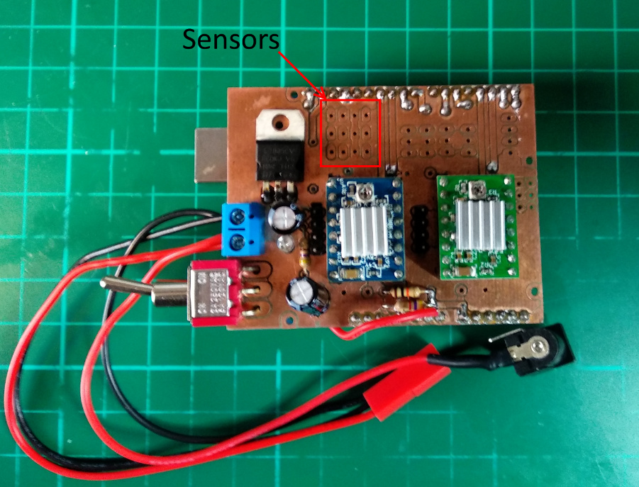
Hey. So I am trying to assemble a robot car that avoids hitting walls. To do this I am planning to use the VL53L0X sensor. The difficulty is using the two sensors.
For a little while I had it almost working however the values were not actual readings. Currently however the code is not getting past the sensor1.init(true) line.
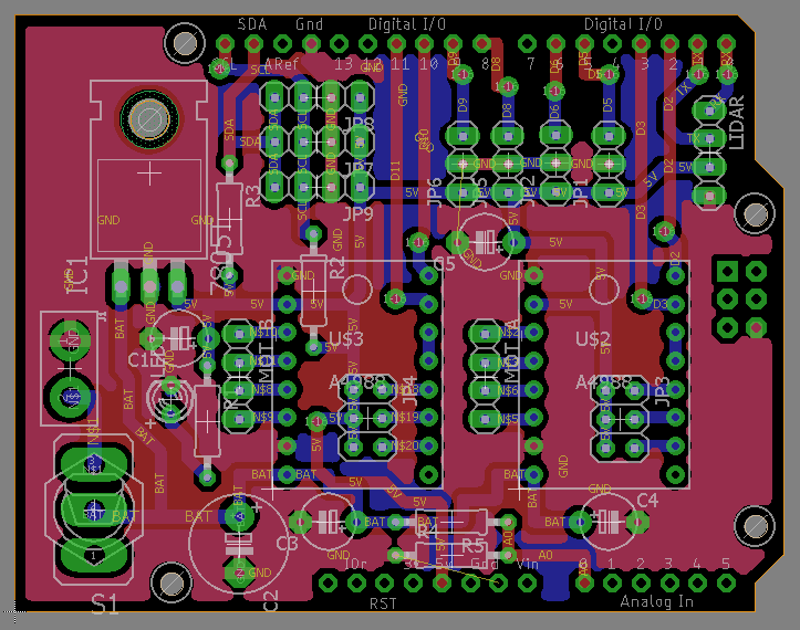
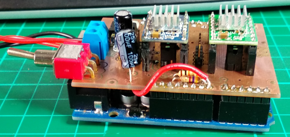
Any suggestions would be appreciated. One other consideration is that I am using a custom shield so I don’t have the ability to use the XSHUT pin.
#include<Wire.h>
#include <math.h>
#include <MPU6050_tockn.h>
#include <VL53L0X.h>


//MPU-6050
MPU6050 mpu6050(Wire);


//VL53L0X
VL53L0X sensor1;
VL53L0X sensor2;

//IR
int IR_1 = 5;
int IR_2 = 6;
int IR_3 = 8;
int IR_4 = 9;


//A4988
int Step_A = 11;
int Dir_A = 10;
int Step_B = 3;
int Dir_B = 2;

int value = 0;
int Index;
char Selection;
int SensorValue;

void setup()
{

  //Serial
  Serial.begin(9600);


  //MPU-6050
  Wire.begin();
  mpu6050.begin();

  //VL53L0X
  Serial.println("S1 start");

  sensor1.init(true);

  Serial.println("01");
  delay(100);
  sensor1.setAddress((uint8_t)22);
  Serial.println("02");

  delay(150);

  Serial.println("S2 start");
  sensor2.init(true);
  Serial.println("03");
  delay(100);
  sensor2.setAddress((uint8_t)25);
  Serial.println("04");

  Serial.println("addresses set");

  sensor1.setTimeout(500);
  sensor1.startContinuous();

  sensor2.setTimeout(500);
  sensor2.startContinuous();

  //IR
  pinMode(IR_1, INPUT);
  pinMode(IR_2, INPUT);
  pinMode(IR_3, INPUT);
  pinMode(IR_4, INPUT);


  //STEPPER MOTORS
  pinMode(Step_A, OUTPUT);
  pinMode(Dir_A, OUTPUT);
  pinMode(Step_B, OUTPUT);
  pinMode(Dir_B, OUTPUT);

  shortMenu();
}

void loop()
{
  if (Serial.available()){
    Selection = Serial.read();

    switch (Selection)
    {
      case '1':
      {
        Serial.println(F("************* TESTING STEPPERS MOTORS - A4988 ******************"));
        testSteppers();
        break;
      }
            case '2':
      {
        Serial.println(F("******************* MESURING VOLTAGE INPUT *********************"));
        mesureVoltage();
        break;
      }
           case '3':
      {
        Serial.println(F("*************** TESTING GYROSCOPE - MPU6050 ********************"));
        displayGyro();
        break;
      }
           case '4':
      {
        Serial.println(F("**************** MESURING DISTANCE - VL53L0X *******************"));
        displayVL53L0X();
        break;
      }
           case '5':
      {
        Serial.println(F("******************* TESTING IR LIMITERS ************************"));
        displayIR();
        break;
      }
    }
  }
}

//********************** TEST STEPPERS MOTORS **********************
void testSteppers() {
  Serial.println(F("MOT_A: RIGHT"));
  turnRight(Dir_A, Step_A, 100);
  delay(1000);
  Serial.println(F("MOT_B: RIGHT"));
  turnRight(Dir_B, Step_B, 100);
  delay(1000);
  Serial.println(F("MOT_A: LEFT"));
  turnLeft(Dir_A, Step_A, 100);
  delay(1000);
  Serial.println(F("MOT_B: LEFT"));
  turnLeft(Dir_B, Step_B, 100);
  delay(1000);
  Serial.println(F("MOT_A & MOT_B: RIGHT"));
  turnRight(Dir_A, Step_A, 100);
  turnRight(Dir_B, Step_B, 100);
  delay(1000);
  Serial.println(F("MOT_A & MOT_B: LEFT"));
  turnLeft(Dir_A, Step_A, 100);
  turnLeft(Dir_B, Step_B, 100);
  shortMenu();
}

void turnRight(int Mot_Dir, int Mot_Step, int spd) {
  digitalWrite( Mot_Dir,HIGH);
  for (int i =0; i <= 3000; i++){
    digitalWrite(Mot_Step, HIGH);
    delayMicroseconds(spd);
    digitalWrite(Mot_Step, LOW);
  }
}

void turnLeft(int Mot_Dir, int Mot_Step, int spd) {
  digitalWrite( Mot_Dir,LOW);
  for (int i =0; i <= 3000; i++){
    digitalWrite(Mot_Step, HIGH);
    delayMicroseconds(spd);
    digitalWrite(Mot_Step, LOW);
  }
}

void turnMotors(int Mot_Dir_A, int Mot_Step_A, bool dir_A, bool turn_A, int Mot_Dir_B, int Mot_Step_B, bool dir_B, bool turn_B, int spd) {
  if (turn_A == true && turn_B == true){
    //TURN BOTH
    if (dir_A == true && dir_B == true){
      //TURN A and B RIGHT
    } else if( dir_A == true && dir_B == false) {
      //TURN A RIGHT and B LEFT
    } else if ( dir_A == false && dir_B == true) {
      //TURN A LEFT and B RIGH
    } else {
      //TURN A LEFT and B LEFT
    }
  } else if (turn_A == true && turn_B == false) {
    //TURN A ONLY
    if (dir_A == true) {
      //TURN A RIGHT
    } else {
      //TURN A LEFT
    }
  } else if (turn_A == false && turn_B == true) {
    //TURN B ONLY
    if (dir_B == true){
      //TURN B RIGHT
    } else {
      //TURN B LEFT
    }
  }
}


//********************** BATTERY VOLTAGE **********************

void mesureVoltage() {
  SensorValue = .0;
  for (Index = 0; Index < 10; Index++){
    SensorValue += analogRead(A0);
    delay(100);
  }
   float voltage = (SensorValue/Index) * (15.5 / 1023.0);
   Serial.println((String)"Input power: " + voltage + (String)" V");
   shortMenu();
}

//********************** MAIN MENU **********************

void shortMenu() {
  Serial.println(F("****************************************************************"));
  Serial.println(F("* 1.Stepper Motors | 2.Voltage | 3.MPU-6050 | 4.VL53L0X | 5.IR *"));
  Serial.println(F("****************************************************************\n"));
}

//********************** TEST MPU6050 **********************

void displayGyro() {
  mpu6050.calcGyroOffsets(true);
  Serial.println();
  for (int i = 0; i <= 300; i++){
    mpu6050.update();
    Serial.print("angleX : ");
    Serial.print(mpu6050.getAngleX());
    Serial.print("\tangleY : ");
    Serial.print(mpu6050.getAngleY());
    Serial.print("\tangleZ : ");
    Serial.println(mpu6050.getAngleZ());
  }
  shortMenu();
}

//********************** TEST VL53L0X **********************

void displayVL53L0X() {
  for (int i = 0; i <= 300; i++){
  //Serial.println((String)"S1 Distance: " + sensor1.readRangeContinuousMillimeters() + (String)" mm");
  //delay(1000);
  Serial.println((String)"S2 Distance: " + sensor2.readRangeContinuousMillimeters() + (String)" mm");
  if (sensor1.timeoutOccurred()) { Serial.print(" TIMEOUT"); }
  if (sensor2.timeoutOccurred()) { Serial.print(" TIMEOUT"); }
  }
  shortMenu();
}

//************************* IR *************************

void displayIR() {
  for (int i = 0; i <= 300; i++){
  String ir_1 = ( digitalRead(IR_1) == HIGH ) ? "On" : "Off";
  String ir_2 = ( digitalRead(IR_2) == HIGH ) ? "On" : "Off";
  String ir_3 = ( digitalRead(IR_3) == HIGH ) ? "On" : "Off";
  String ir_4 = ( digitalRead(IR_4) == HIGH ) ? "On" : "Off";
  Serial.println(ir_1 + (String)" | " + ir_2 + (String)" | " + ir_3 + (String)" | " + ir_4);
  }
  shortMenu();
}

void Test()
{
  Serial.println ("I2C scanner. Scanning ...");
  byte count = 0;


  for (byte i = 1; i < 120; i++)
  {

    Wire.beginTransmission (i);
    if (Wire.endTransmission () == 0)
    {
      Serial.print ("Found address: ");
      Serial.print (i, DEC);
      Serial.print (" (0x");
      Serial.print (i, HEX);
      Serial.println (")");
      count++;
      delay (1);  // maybe unneeded?
    } // end of good response
  } // end of for loop
  Serial.println ("Done.");
  Serial.print ("Found ");
  Serial.print (count, DEC);
  Serial.println (" device(s).");

  delay(3000);
}