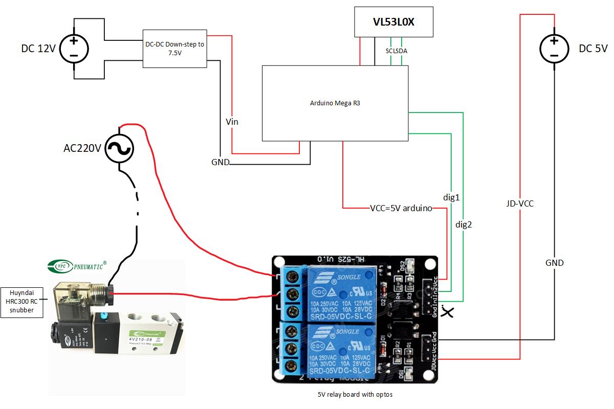
Problem: the arduino Mega keeps resetting from time to time (1 to 30 minutes) although a RC snubber is installed for this solenoid valve. The solenoid works with 220VAC. I use two DC sources (one for logic, one for optos).
The VL53L0X displays a totally erroneous value just before the arduino resets or the value is erroneous and the arduino keeps working.
Note that AC220V are shielded with shields grounded. Optocouplers “should” avoid interference between logic and power circuit, so far I think their connection is correct? maybe a ground loop or ground issue?
How long are the I2C wires between the VL53L0X sensor and the microcontroller in your system? Do they run close to any high current wires? What kind of erroneous values are being returned? If you post pictures of the sensor board and connections, I can look for problems. Also, bad communication between the sensor and the microcontroller might cause the code on the microcontroller to freeze, but we generally would not expect it to reset itself after that. A power supply issue or short circuit somewhere else in the system could cause a reset.
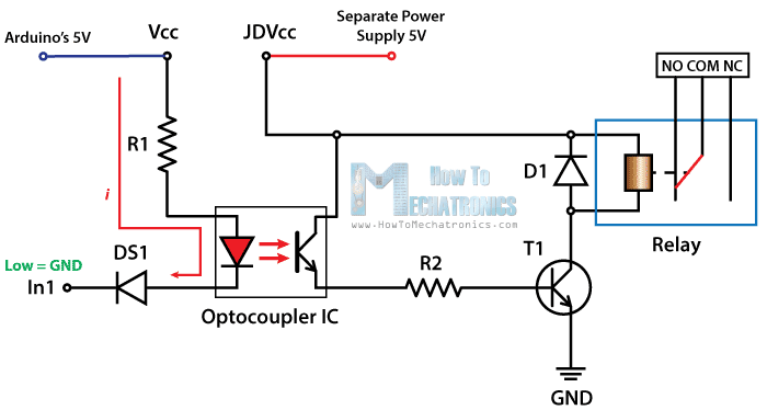
There needs to be some sort of ground between the relay board and the microcontroller for the 5V supply from the Arduino to do anything, though if that line supplies power to the positive side of the LED in the optoisolators and the dig1 and dig2 lines in your diagram ground the negative side of the LED to turn it on, that could work OK.
For i²C, I use a range the polulu item “I²C Long-Distance Differential Extender”. The master extender is directly on the board at 2 cm from the arduino then I use STP ethernet cable for 4 meters then the slave range extender and 30cm of cable to reach the sensor.
I tried to route signal cable away from 220AC cables, the last ones are shielded. The both DC sources/AC sources are connected to the same AC power generator (diesel motor).
The erroneous value returned is 65535 (max unsigned int), will appear when the solenoid valve moves (within a few moves). I tried the circuit with a light bulb (resistive load) and it works OK.
I have changed the 220AC coil with 12VDC solenoid coils, and used a 12V car battery to power the solenoid coil and I kept the DC12V/DC5V on my power generator, the crash still occurs (ground loop, EMI?).
Although I made the circuit for full isolation between logic/power, you suggest I should connect the GND of both DC (5V and 12V) sources together?
If your power leads to the sensor are as long as the data leads, it would be prudent to add an electrolytic capacitor (100uF or so should be sufficient) to the VIN for the sensor near the PCB.
Is the object the sensor is measuring the distance to also moving when the solenoid valve moves? Is it possible to try to move the object without activating the solenoid? What library are you using to read the sensor? Our library returns values of 8190 or 8191 when it can no longer read the distance to an object, but it is possible another library would return the value you indicate.
We are not familiar with the relay board you posted, so we do not know if the logic signals need a ground connected, but it is possible they do. If you have a schematic for the board, you might check to see how the optoisolators are connected to the I/O pins.
The problem is maybe dealing with the transient voltage: the RC snubber manual says “reduce transient from 10/20 times nominal voltage to below 2.5 times”, meaning I can still have a 550VAC peak at the relay on (de)activation. The relay isolation is 500VAC, so it could have some leak. And the circuit/laser work fine with a light bulb instead of the solenoid valve.
I already tried 330uF (35V) capacitor at the sensor board (less than 2 inch distance) without success. I purchased some TVS diodes to put at the relays to test next week.
OK, that schematic looks like what I was trying to describe a few posts ago, so your connections there look OK. At this point, it seems like you have isolated the problem to some kind of electrical noise from the solenoid. Adding a flyback diode to your 12V coil (or TVS to the AC coil) might help. The D1 diode in the diagram you posted acts as a flyback diode for the coil on the relay (which is probably only a little less powerful than the coil on your solenoid valve).
Also, the shielding in your shielded cable should be connected to ground at one end of the cable if you are not already doing that. In general, I2C can be susceptible to noise (which still seems to be a potential cause of your issue).
By the way, have a machine here with an air valve that looks very similar to the one you posted that uses a 12V 2.5W solenoid coil. We use a single 12V supply for a microcontroller and motor driver (with 100uF electrolytic capacitors at the supply points of those two components) to drive the air valve’s solenoid coil. The FETs in a motor driver like that have a built-in diode that functions like the D1 diode in that schematic. Our system is a little different from yours. We do not have any sensors or use I2C on the system, but we also do not use any special isolation or shielding and our system has been working for a few months now. Using three separate power supplies just seems to me like it might be a little more complicated than needed.
Thanks for the paper. I was able to improve my circuit: my cable from the relay to the solenoid coil was 5 meters long and there was an inductance issue with the cable. I added a emi line filter (LRC filter) and it works fine now - I think a second RC filter at the relay could work too -, whatever is the cable length. I am using twisted pair cable to connect the solenoide too.
BUT…
Upon adding a second VL53L0X, the second sensor reading had tendency to crash frequently. So I changed my relay (mechanical coil) with a solid state relay. I am now able to run 5 VL53L0X but the sensibility to interference is very strong: switching off a couple of light bulb in my house crashes the reading. More VL53L0X = increased unstability in the bus. So, I now run my arduino on 12V battery instead of power grid. 400kHz i2c bus speed is stable too.
Note that every sensor is connected to a sjbit i2c range diferential extender board with less than 50 cm cable. There is about 1m between each extender board. Shielded STP cable between.
What is the capacitance of each VL53L0X module? it seems to be the starting point to calculate optimal pullup.
From my understanding, it is impossible to use mechanical relays (with opto or not) to switch solenoides valves while using more than one VL53L0X. Arcing/EMI are a big problem with i2c bus stability. Even with a proper RC module at the solenoide valve and a EMI line filter to isolate the AC circuit and twisted pair cable.
Do you have any tips to improve i2c bus stability when using 5 VL53L0X sensors?
PS: if you still have your circuit with MOSFET/solenoid valve, try adding 5 VL53L0X to see the stability.
We have not characterized the I2C bus capacitance of the board itself, but (as that Hackaday article I mentioned before discusses) your wires will add some stray capacitance too. If you are concerned about transition times on your I2C bus, you might use an oscilloscope to look at the signals. Keep in mind that stray capacitance will increase the amount of energy from a noise source necessary to change a bit, so the capacitance of the board doesn’t seem to be related to your problem. Still, a stronger pullup resistor will also increase the stability of the bus.
Other than the resources I have already posted, we do not have any specific suggestions for reducing noise in your I2C bus.
Yes, I reviewed many documents on I2c bus capacitance, and the only way to optimize it is using an oscilloscope.
Nonetheless, I made some tests with my 5 sensors and my Solid-state relay, involving 3 differents power sources.
The arduino running on 12V battery, while solenoide are powered on 220VAC from a DC inverter (solar system). RC filter on the solenoide. This setup runs fine at bus speed from 10kHz to 500kHz (set via wire.setClock) with solenoide working.
If I turn on any small motor in the same room (motor using the power grid 220VAC), the last 3 sensors ready go crazy. It’s highly sensible to EMI radiation, whatever the frequency is. Cables were not shielded in this test. I am doing modifications to my shielded setup and see if it can handle realword noise.