Hi,
Good Scenario :
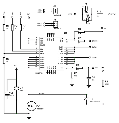
I have designed a motor controller using vhn2sp30 motor driver from ST microelectronics similar in schematic to pololu motor driver and Atmega328P is the controller. I power on the microcontroller from a different source (USBasp is connected to PC which turns on atmega328P) and program it using Arduino. I have connected a motor to output pins and when I connect battery power to VHN2SP30 chip, the motor starts running. Everything seems to be working as expected.
Bad Scenario:
The trouble starts the other way around. I connect the battery to VHN2SP30 chip and then power on the Atmega328P chip from another 5v source, but the motor does not rotate. There is also a regulator connected to Battery input which provides regulated 5v supply to AVR chip. Even in this case, the motor does not work. I tried removing the regulator / keeping the regulator. Whatever I do, it does not make the motor rotate. The only way is to power on AVR chip from an external source and then connect the battery.
Very Bad Scenario:
The third scenario is when the battery is connected and the motor is spinning, when I press the reset button, it resets the chip and then the motor stops. I need to remove battery supply to motor driver and reconnect it.
Does anybody know why this might be happening?
More information:
-
There is a 35v, 470uF electrolytic capacitor attached to motor driver power pins
-
A 100uF 10v tantalum capacitor is connected to 5v and Ground pins (to output of regulator)
-
Regulator used is LM1084 from Texas instruments
-
Battery is fully charged with capacity of 2200uA and 11.1V
-
Tried different motors from tiny toy motor to metal gear motors, but the result is the same.
-
There are two LED’s connected which turns on when motor turns on either direction. In the Good scenario (when motor is spinning) the LED turns on to indicate direction. In the bad scenario, when motor is not connected, the LED still turns on to indicate direction. However in the same bad scenario, when the motor is connected, the LED turns off.
-
When the board is in bad scenario, the voltage on motor output pins will be 9v (same as input voltage) and 8.8v (voltage drop). However, on a good scenario, it is 0v in one and 9v on the other. LEDs are bright when the motor is spinning and when no motor is connected, the LED lights up really light.
-
PWM does not work on the board. If motorGo(0, CW, 1023); is not 1023 even in a good scenario, the motor does not rotate. So, the possibilities of motor running are: a. Provide 5v input → Program and make sure PWM is 1023 → Connect battery → Motor Spins.
Can someone help me find a reason or a solution to this issue? Since the board is similar to Pololu board, I thought someone might have an answer to this.
Attached schematic and below arduino code from sparkfun:
#define BRAKEVCC 0
#define CW   1
#define CCW  2
#define BRAKEGND 3
#define CS_THRESHOLD 100

/*  VNH2SP30 pin definitions
 xxx[0] controls '1' outputs
 xxx[1] controls '2' outputs */
int inApin[2] = {7, 4};  // INA: Clockwise input
int inBpin[2] = {8, 9}; // INB: Counter-clockwise input
int pwmpin[2] = {5, 6}; // PWM input
int cspin[2] = {2, 3}; // CS: Current sense ANALOG input
int enpin[2] = {0, 1}; // EN: Status of switches output (Analog pin)

int statpin = 13;

void setup()
{

  pinMode(statpin, OUTPUT);

  // Initialize digital pins as outputs
  for (int i=0; i<2; i++)
  {
    pinMode(inApin[i], OUTPUT);
    pinMode(inBpin[i], OUTPUT);
    pinMode(pwmpin[i], OUTPUT);
  }
  // Initialize braked
  for (int i=0; i<2; i++)
  {
    digitalWrite(inApin[i], LOW);
    digitalWrite(inBpin[i], LOW);
  }
  // motorGo(0, CW, 1023);
  // motorGo(1, CCW, 1023);
}

void loop()
{
  motorGo(0, CW, 1023);
  motorGo(1, CCW, 1023);
  delay(500);


  if ((analogRead(cspin[0]) < CS_THRESHOLD) && (analogRead(cspin[1]) < CS_THRESHOLD))
    digitalWrite(statpin, HIGH);
}

void motorOff(int motor)
{
  // Initialize braked
  for (int i=0; i<2; i++)
  {
    digitalWrite(inApin[i], LOW);
    digitalWrite(inBpin[i], LOW);
  }
  analogWrite(pwmpin[motor], 0);
}

/* motorGo() will set a motor going in a specific direction
 the motor will continue going in that direction, at that speed
 until told to do otherwise.

 motor: this should be either 0 or 1, will selet which of the two
 motors to be controlled

 direct: Should be between 0 and 3, with the following result
 0: Brake to VCC
 1: Clockwise
 2: CounterClockwise
 3: Brake to GND

 pwm: should be a value between ? and 1023, higher the number, the faster
 it'll go
 */
void motorGo(uint8_t motor, uint8_t direct, uint8_t pwm)
{
  if (motor <= 1)
  {
    if (direct <=4)
    {
      // Set inA[motor]
      if (direct <=1)
        digitalWrite(inApin[motor], HIGH);
      else
        digitalWrite(inApin[motor], LOW);

      // Set inB[motor]
      if ((direct==0)||(direct==2))
        digitalWrite(inBpin[motor], HIGH);
      else
        digitalWrite(inBpin[motor], LOW);

      analogWrite(pwmpin[motor], pwm);
    }
  }
}

