Versatility of Orangutan USB programmer

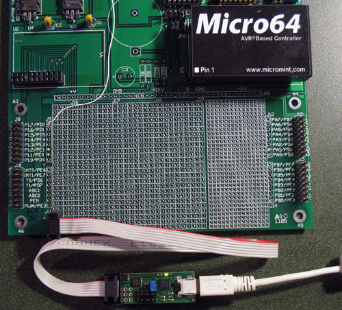
Although Pololu does not guarantee that their Orangutan USB programmer will work with other AVR MPUs, it is remarkably versatile and in fact, I prefer now prefer it to the much more finicky AVRISP mkII. I’m taking a moment here to show that it works well with the AVR Butterfly (which runs at 2.7 - 3.6 V) as well as the atmega64, as implemented in Micromint’s Micro64 module (which includes other hardware such as a real time clock, 32KB external SRAM, etc.). Both MPUs presented issues that required some study before attaching the programmer! My development system is WinXP/AVR Studio 4.13/WinAVR_20070525.

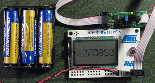
First, programming the Butterfly turned out to be straightforward, if you get the ISP connector on the right way and also, the Butterfly operating voltage has to be at least 3.3 volts. I soldered a 6-pin header to the Butterfly ISP port as described in the Butterfly User Guide and determined that the proper connection is with the ISP cable passing over the joystick as shown in the photo below. This setup will not work if the Butterfly is powered by the 3.0 V lithium coin cell, but it has been 100% reliable if powered by 3 NiCAD batteries (3.6 V) from an external battery pack as shown. I wrote a small RTC program, with an intuitive joystick interface for setting the clock, that can you can download from the Projects section of AVRFreaks (Butterfly_RTC_demo). Needless to say, you have to set the correct MPU type (atmega169) in AVR Studio.

Second, the atmega64 has a weird ISP interface and an extra programming input *PEN, which is said to “enable the serial ISP programming interface if held low while power is applied. *PEN has no other function during normal operation”. Also during programming, the IO pins are remapped so that the designated ISP pins MISO and MOSI (PB3 and PB2) get remapped to PE1 and PE0. *PEN has caused much confusion and there are conflicting reports on the internet as to whether *PEN needs to be grounded, left floating, or tied high. The atmega64 data sheet is amazingly unclear on the use of *PEN, as well. In fact, I have not been able to find a useful account that described in detail how to use an AVRISP-like 6-pin programmer with the atmega64. Finally, the Micromint module has a *RESET input, but the Micromint folks do not tell you how it is connected internally within the module.

My approach was to try various things and presumably due to clean living, the first attempt worked! I was able to program the atmega64 with the following connections to the ISP header (again using AVR Studio 4/gcc).

*PEN – left floating (I’m worried about the reliability of this and will try some other options).

Pin 1: PE1 (MISO)
Pin 2: open
Pin 3: PB1 (SCK)
Pin 4: PE0 (MOSI)
Pin 5: *RESET
Pin 6: Ground

Good job, Pololu! Comments welcome.

Cheers, Jim

1 Like

Hey Jim, long time no, uh, post.

Anyway, I’ve recently been using some ATMega128s which appear to be the same as ATMega64s with twice the flash and eeprom (same pinout, same peripherals, they even both have an “ATmega103 Compatibility Mode”). How odd that they have separate datasheets then. I was also similarly confused about programming them at first. I’m assuming that their *PEN pins are the same, and the ATMega128 datasheet gives slightly more information:

Actually I’m certain the ATMega64’s PEN is internally pulled high as well, since the DC Characteristics Table on page 325 of the ATMega64 datasheet lists Rpen, the internal PEN pull-up resistance (20Kohm-50Kohm), so leaving it disconnected isn’t actually leaving it floating. Also, if you look at Figure 147 on page 306 of the ATMega64 datasheet, they show the necessary connections for SPI programming, and *PEN isn’t even pictured! They even include a reference voltage applied to AVCC in the diagram, so I assume they’re showing you everything you need to connect. The only mention of *PEN I was able to find in the programming section is in the power-up sequence on pages 306-307:

Well, I guess that’s what it does, I have no clue what it’s good for or why you would want or need to use it. I have never used this pin, and never had a problem programming the ATMega128 by just connecting the reset line to the programmer as usual. Well, that’s not entirely true. It took me a while to spot that weird thing you pointed out that the MISO and MOSI pins are remapped to the TX and RX pins from one of the UARTs (lame!) during SPI programming. I think that should have been flagged on the pin configuration diagram on page 2. Oh wait, it is, I just didn’t know what PDI and PDO stand for. Anyway, SINCE I figured that out and rewired my programming header accordingly I haven’t had any problems programming, without touching *PEN.

Glad to hear that the Pololu USB programmer is so versatile and robust, finicky is probably too polite a description of the AVRISPs. I’ve been toying with the idea of picking one up just because (they’re so small!), but I can’t really justify it when I’ve already got two AVRISPs at work (mkI and mkII) and one (mkII) at home. Oh well.

-Adam

Hi, Adam:

I have been living in Auckland, New Zealand (what a paradise!) and did not have Orangutan-related items with me while there. Hence no posts. I’m now back in the states and do have some new projects in mind.

Thanks for pointing out the pullup on *PEN. Figure 22, page 52 in the atmega64 manual suggests that *PEN acts like *RESET, except that it only functions during power up when the signal is passed through the latch. I had overlooked the pullup resistor in that diagram and won’t worry further about connecting *PEN. I wonder, though, what the engineers were thinking when they added *PEN and wrote the description. It may have something to do with executing a serial port bootloader in high memory upon power up, which is how the Micro64 is configured. As the unfortunate description now stands, *PEN has caused much confusion.

Jim