I am attempting to use a uv370a to drive the input of an led headlight which accepts variable input voltage at the cost of lower output power at lower input voltage. I’m guessing it uses a DC to DC regulator at its input stage. The light is a black box to me and no data is available regarding input requirements other than average power / current at given input voltage but from what I can see it has some kind of switching on the input which results in input current transients. I am trying to maximize the output power of the light and thus the output voltage of the pololu voltage regulator.
My power source is current limited both in peak and average current. (About 20% higher transient allowed)
If I use a simple tantalum 100 uf capacitor directly in parallel with the light input it trips the current limits for my source on startup.
If I use no output capacitor the ripple is too much for the DC to DC converter on the light and it fails to startup as I increase the input voltage above a power level that is well within the supplies limits which I’m assuming means the current transients are too much for the pololu regulator to supply.
If I use a 66 uf tantalum output capacitor it starts up successfully and runs the light for approximately 45 seconds at a power level well above the no capacitor cutout but the tantalum capacitor begins to heat significantly and then I’m assuming the effective capacitance drops and the light power supply drops out of regulation.
Any suggestions on output capacitance selection or more complex circuits that could be employed?
I was reading that parallel combinations of ceramic and electrolytic output capacitors may be more stable in temperature.
Thanks. Yes I am trying to figure out alternative arrangements with different construction of caps however I am not finding application notes from Pololu on guidelines for what the regulator expects.
Here is an update that has me even more perplexed. I was trying to understand what was causing the tantalum cap to heat up and that lead me to discover that the one cap was in fact polarized (where my other tantalums were not) and I had it in backwards. Reversing that fixed the heat issue.
However,
When placed properly the output filter does not provide an improvement to the voltage I can apply to the light system over just running without additional output capacitance.
In my scope the startup voltage waveform from power on looks largely the same (linear ramp with the occasional flat interruption) with the cap in either direction.
With the cap in the correct direction the light flashes very briefly and then shuts off indicating an error with the incoming power.
With the cap in the wrong direction the light comes on and stays on solid for as I mentioned about 45 seconds at which point the cap has heated up and then the light power supply switches to the error mode.
What is different between the two cases is the waveform after power up. In the case of the light running for 45 seconds the regulator has a large voltage ripple ( close to .7 v). I haven’t been able to figure out a trigger condition to see what’s happening after startup when the regulator with the capacitor mounted the right way causes the light to indicate error.
I’m trying to figure out what to try next to get a cap in the proper orientation to cause the light to work. My current guess at this point given that the reverse polarity cap is heating up is that orientation causes additional series resistance so I am thinking to try adding a low value power resistor in series. The only other thought I had may be a change in inductance.
Unfortunately with the light being a black box I can only guess at what it is not liking about the input power.
Our regulators do not need any extra capacitance or load to work by themselves. This issue seems pretty specific to your system, so it is hard to make any suggestions without knowing more.
How much current does your light draw from the regulator at 7.5V? Could you post a link to any documentation for the light? Could you post some pictures from your oscilloscope of the startup waveform at the regulator’s VIN and VOUT? Scope captures both when it works and when it doesn’t would be helpful.
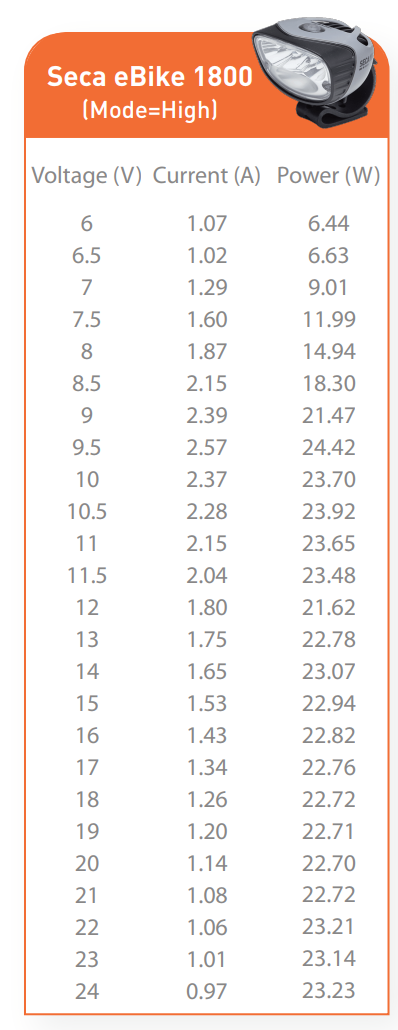
as to input current, i don’t have a current probe yet so hard to see instantaneous I will pick one up today to measure. However, when I connect to my bench power supply instead it is indicating current consumption that roughly matches the chart below that is published from the light manufacture (seca e in the below image) for given voltage. Note this is the only form of spec I can find for the light.
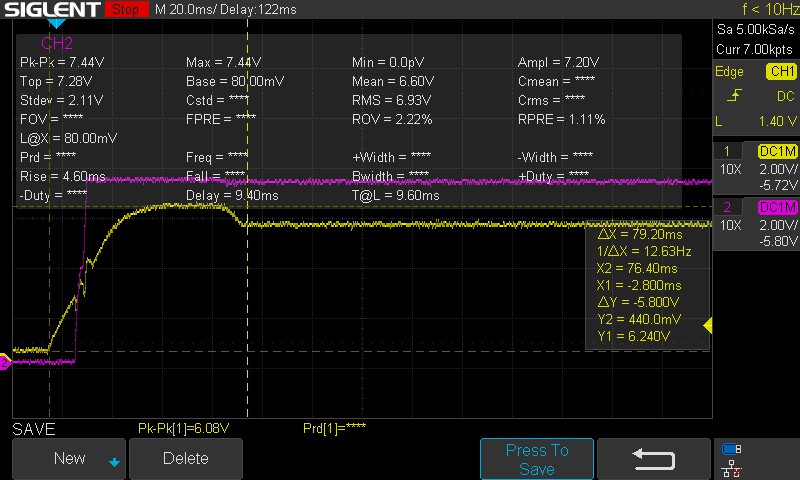
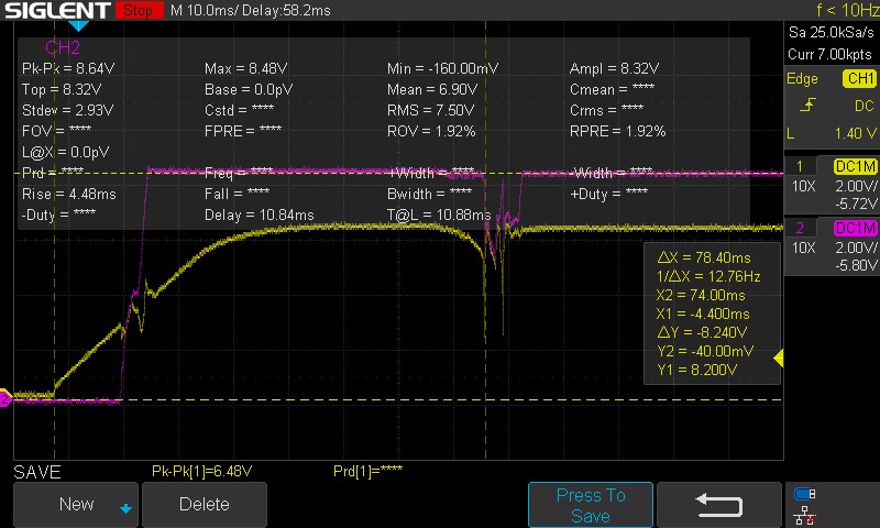
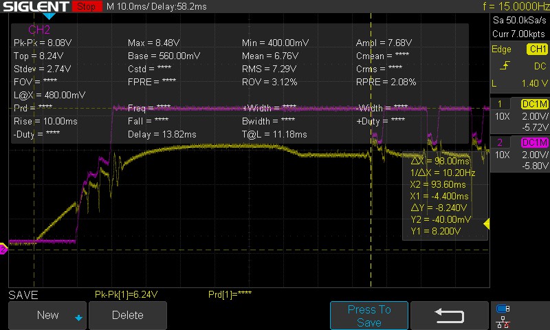
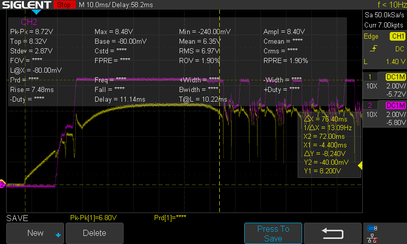
In all scope traces, ch1 = vin, ch2 = vout
first scope capture is the case where the boost converter is successfully taking my 6.1 v input and boosting to ~7.4 v at startup. No additional capactiors
second scope capture is no output capacitance, higher vout, where the light fails to start
third plot is output capacitance of ~66uf, tantalum polarity reversed. Note my poor cap is probably frying as it no longer stays running for very long and the light only comes on very briefly before hitting the error state.
fourth plot is output capacitance of 66uf installed with correct polarity. In this case the light fails to start and corresponds to the high dropout spike I think shown in this plot shortly after achieving output voltage
What is interesting is obviously there is some input drop out with some kind of sudden demand.
The power source has an automatic cutout detection when it’s current limit is exceeded, which i can cause by putting a higher value capacitor on the output. (in regular orientation) This shows up as vin being shutoff entirely, and an error code displayed on the bike. In these plots this does not happen so I suspect that the current demand is not much exceeding the 3.5A limit at 6v.
Thanks for the additional information. I can see the voltage of your supply dropping intermittently in the scope captures where the system fails. If your 6V supply has a 3.5A limit, that means it is limited to 21W. The U3V70A regulator is not 100% efficient, so that seems pretty close to the 18.3W rating of your light at 8.5V. It would not be surprising if the light draws a little extra on startup, and adding a capacitor to the output of the regulator would also add to the startup draw from the power supply, since it need to charge up. I suspect your supply is not quite powerful enough.
Please try adding a large capacitor (100uF or more) to the input of the regulator. Then, hold the regulator disabled while the supply turns on and charges the input capacitor. Lastly, enable the regulator and light and see if that affects how VIN and VOUT look on the scope.
Thanks for the update, to be clear the drop out of the light starts happening just over 7.5v of light input or approximately 12 W and looks roughly the same as the 8.5v signals.
Regardless, I will give the idea of holding it to start until after the cap has charged a shot.
I have tried a 100uf cap as input filter with the regulator also starting up and that tripped the over current almost immediately at startup.