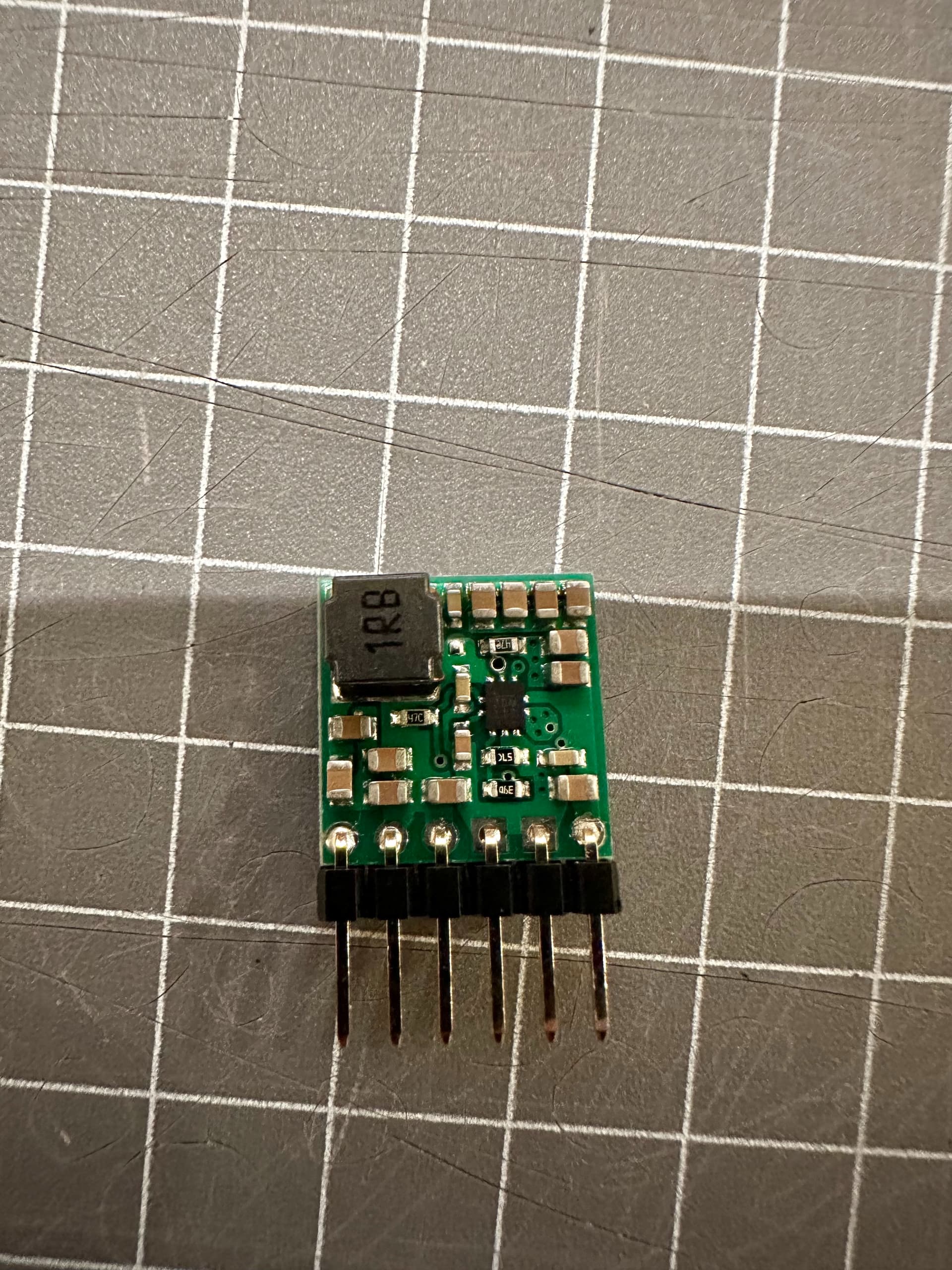
Hi there, I bought a U3V40F7 step-up regulator with the hopes that it will be able to power my DS5180 servo motor but I have been having some issues.
Setup
Meanwell 5V 14A power supply → PCA9685 servo motor driver → U3V40F7 → servo motor.
Issue description
I can power the PCA9685 and servo motor directly from the Meanwell power supply (adjusted to 5.7V) and use the servo to lift half of a robotic arm without stalling if I put resistance on it. I can see on my multimeter that the peak current draw of the servo is about 500mA during this lifting operation, and about 1A if I put resistance on the servo’s movement. However, I decided that I wanted a bit more torque and purchased the U3V40F7 to step up the voltage to 7.5V. I can see on your product description that for my input voltage of 5.7V, the max continuous output current should theoretically be about 2.8A, which should be enough for my use case.
However when I use the U3V40F7, it is able to lift the arm but any small resistance or faster speeds will cause the servo to stall and it just stops its expected motion and jitters around. The regulator output current just before it stalls is 400mA. When stalled, V_out drops down to 7.2V. Maybe the regulator does not provide enough current quick enough? I know that it can provide at least 1.5A continuously as I tested this using a source-measure unit but it may be that it cannot provide enough instantaneous current during the servo’s movement and the servo shuts off. What do you think? The other clue is that if I set the servo to hold a position (no movement), the regulator does not have a problem with this and I can put as much resistance on the arm as I want and it will barely budge, so it seems the problem is only during movement.
What do you think is causing this problem and can I fix it using additional electronics?
Could you post some pictures of your setup that show all of your physical connections, including close up pictures of both sides of your board? Can you also try monitoring your setup with an oscilloscope?
Additionally, it would also be helpful if you post a datasheet or a product page link for the servo.
I think all of your connections look okay, but can you try powering the regulator directly from the supply (instead of through the servo controller) to see if that affects the results?
When you are able to access a scope, I suggest looking at both the power into (VIN) and from (VOUT) the regulator to see if either of them ever drop out. Double checking that the servo signal looks okay to be thorough would be a good idea too. Then, I suggest comparing those results to what happens on the power line if you connect your 5V supply directly to the servo.
Hi Patrick, I’ve managed to get an oscilloscope to monitor the voltage signal. I took videos for the regulator V_out and V_in and for the 5V supply V_out: Oscilloscope videos
It looks like the regulator V_out actually drops down to 5V (V_in??) when under a heavy load (when the arm is lifted up from a horizontal position) with some spikes up to 7.5V. V_in stays roughly at the same voltage but there are corresponding spikes down to ~3.5V. By contrast the 5V supply seems to do fine, a slight voltage drop when there is a load but only by like 0.3V and no spiking.
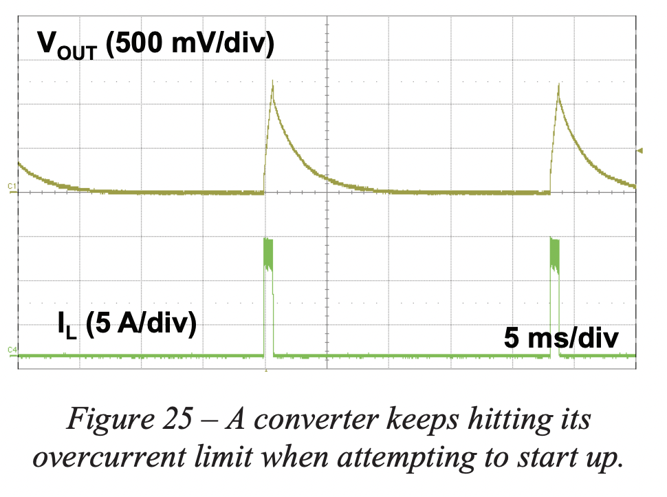
Seems in general that the regulator can’t really deal with the changing load of the servo. Maybe it’s not meant for variable loads? I found this resource from TI that describes a very similar-looking problem in Section VII (Figure 25) where the regulator continually tries to boot up but over-current protection activates and it resets: DC-DC converter common problems.
I’m not an expert in this though, so do you think there would be a way to correct this for my specific use case? Or should I just try to look for a different way of powering the servo at 7.5V?
Did you try powering the regulator directly from the supply instead of through the servo controller, like I suggested in my last post? Does that have any affect on the results?
Yes I did, no change at all from doing that, the same signal appears on the oscilloscope. I know you guys make servos- is there any chance you guys could try to replicate this result when you have time? It would help to narrow down the cause I think. I had this same result when I tried to use a smaller servo.
Could you post more information about the smaller servo you tried using? Did you have any load connected to the smaller servo when you tested it?
The behavior in your scope videos could be from a large burst of current when the servo first accelerates causing the regulator to overheat. One thing you could try to help that is adding a capacitor (maybe in the 100-200 µF range) at the input or output of the regulator to see if that helps.