I am now working on a project, I am using the dual serial motor controller to control a cheap remote controlled car. However I found that when I send commands to move the motor forward at full speed, the motor would just move for 3 seconds and then just stop. May I know the reason?
Power Supply : a battery pack containing 6 AA batteries
Commands used: SEROUT 4, 84 (80, 0, 3, 127)… am using the Do…Loop as well
I notice that when I reduce the speed from 127 to 50, the motor can move non-stop… but when I changed it to full speed which is 127, the motor would just move for few seconds and then stop…
You’re probably drawing too much current for the motor driver, causing the over-temperature shutoff to kick in. What kind of current are you expecting?
Hi, I connected the battery pack of 9V, which contain 6 AA batteries, to the DC motor.
So while the motor is turining, I place my multimeter in series between the power supply and the motor, and I got 5mA. Is it right?
To make things easier, the red probe of my multimeter is on the battery pack’s red line, while the black probe of the multimeter is on the DC motor’s red line. Is that the correct procedure?
The remote controlled car I am using is a cheap one…
From what you are saying, it sounds like you are using your multimeter correctly, but if you got 5mA, you are probably doing it wrong somehow. As an example, this motor is a typical cheap hobby motor, and it will draw at least 100mA at 9V, probably increasing to 200 or 300mA if you connect gears and wheels to it. Could you possibly take a picture of your setup when you are measuring the current so that we can see exactly how you have wired things up?
What I meant was a real picture taken with a digital camera to convince me that your motor is only drawing 5mA. How big/heavy are the motors? Most remote controlled cars will take much, much more current than that, and if you don’t know what it is, you might be taking more than the motor controller can handle.
So for the drawing that I attached, is it the right way to measure the current?
I want to confirm that this is the right way to measure. Then perhaps I can take the picture to show you
Yes, that’s the right way to connect it - but make sure you are using the current connections for your multimeter and that you have it set to current mode.
I am sorry. But I think there is sometime wrong with the way I connect it on the breadboard.
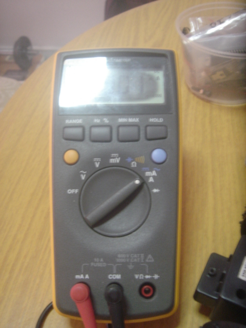
I have attached the breadboard drawing for you and the multimeter I used.
I measured 2mA!!! I think the problem lies with me…
Kindly advise
Your new drawing including the breadboard makes it clear! You can tell that you aren’t measuring a current this way because the motor still spins when the meter is not plugged in - that means the current is not flowing through the meter. You need to set the circuit up as a single loop, with the battery, meter, and motor all in series. For example by putting the + lead of the motor and the + lead of the battery in different breadboard rows, so that the motor doesn’t turn until you connect the two rows through the multimeter.
Thanks a lot for your enlightenment!!
I made such a silly mistake. The current gotta move through the meter for measurement. I am sorry for the inconvenience caused.
Okay, for my car, I have the steering wheel which is controlled by Motor1
The forward and reverse movements are controlled by Motor2. With gears and wheels attached.
The measurements are as follows,
Motor 1 = 950mA
Motor 2 = 250mA
Battery supply : 9V battery pack containing 6 AA batteries.
Problem : When I programmed Motor 2 to turn non-stop at full speed (127), it tends to turn for around 3 secs and then just stop.
When I programmed Motor 1 to turn non-stop at full speed (127), the front wheel will just move to the left and then move back to original center position. It should steer the wheel to the left.
Observations: The motor tends to work obediently when I reduce the speed to around 50.
Kindly advise…
Thanks a lot!
That’s a more realistic measurement, and motor 1 is right at the limit (1A) of what the motor controller can handle. With any extra load, like the weight of the car, it is going to go over 1A, which could cause the behavior you are seeing. Even the 250mA motor will probably take much more current when pushing the car along. Starting and stopping also require the motor to draw very large currents, which could damage the controller. You can measure the maximum current that the motor will ever take - the stall current - by stopping the wheel with your hand when you are making the measurement.
By the way, do you have any idea why the readings from the two motors are so different? Is the behavior different depending on whether the car is on the ground or you are lifting up for testing?
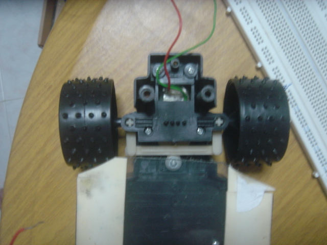
Firstly let me explain why motor1 (950mA) is different from motor2 (250mA).
motor1 controls the front 2 wheels for right and left movements, therefore there is a wheel alignment system attached to this motor. I have attached a picture for your reference. So which means motor1 actually turns a bit before its movement is stopped by this alignment system. In this scenario, the wheels are steered to the left, for example. Whereas for motor2, I tested the motor while lifting the car off the ground for testing.
I have measured the stall current for motor2, and the result is 2.8A. So what can I conclude from this result? Is the motor controller unable to support my motor’s current demand?
So are there any solutions to this problem?
Did I use the wrong motor controller for this project?
Did I use the wrong motor supply for this project?
For your information, this 9V battery pack is also used to power up a solenoid actuator. However the use of the solenoid actuator is just to push out the plunger and back, the movement is minimal.
Just got something to add. The problem that I have encountered is even present when I lift the car up for testing. Which means the wheels did not even touch the ground. There should not be any excessive stress on the motor. Yet the motors are not performing well.
Well, motor1 is right at the limit of what this motor controller can do, and it will definitely be out of its current range when starting. You might be able to get the car to move along if you started the speed at 50 and slowly ramped it up to 127, but if it ever encounters a slight bump or slope, it’s going to be over the current limit again. With motor2, if you try to turn at 127, it’s going to hit the wheels’ limit of motion in a very short time and go over the current limit. Also, does your 9V battery pack start out above 9V? That’s another way you could be over a limit for this controller.
I think you need to go with at least the TReX Jr to control this kind of car.
Hi Paul,
Thanks again for your reply. I have some questions which I hope you can help me to clarify.
"You might be able to get the car to move along if you started the speed at 50 and slowly ramped it up to 127, but if it ever encounters a slight bump or slope, it’s going to be over the current limit again."
May I know the program code to start the motor at speed 50 and then ramped it up to 127. This car is only designed to move on flat surface, I hope this method works. As the project is in its final stages, I do not want to change any hardware.
"does your 9V battery pack start out above 9V? That’s another way you could be over a limit for this controller."
The batteries I have now is only 8.7 - 8.9V range. I have been using them for quite some time. So do you mean that if my battery pack is lower than 9V, it is better?
Can I summarize the problem as below?
The motors in this car need more current than what the motor controller can supply. Therefore the motor will stop when it needs more than 1A.
So are there any solutions to this problem?
I sourced this motor controller on a Parallax website. Then I found out that this product is from Pololu. So is Parallax the distributor for this product?
There’s now way I can give you the code to ramp up your speed, because I don’t even know what controller you are using! But it will definitely be straightforward with any programming language. For example, if you were using a Baby Orangutan with its built-in motor drivers, it would look like this:
I put a very long delay in there - you can adjust it to whatever works for you. If you can’t make it up to 127 without causing the motor controller to overheat, you’ll probably just have to stick with a lower value for now.
Your summary might be a correct explanation of the problem, but we really don’t know for sure until you get it working. Another issue that we haven’t even talked about is motor noise, which could be causing your circuits to act strangely. Take a look at our Application note on motors for a discussion of various things you can do to prevent noise from disrupting things.