Using Pololu USB AVR Programmer v2 to load bootloader on to Adafruit Pro Trinket 3V

Pololu Team:

I’m having a similar problem I’ve been struggling with for a couple days. I’m new to flashing a bootloader, so I’ll apologize in advance for my ignorance.

I have an Adafruit Trinket Pro 3v, which I’m trying to write a bootloader on using the Pololu AVR V2 Programmer. I’m seeing an error which indicates lack of power at VCC. However, when I measure voltage at the Trinket Pro +3v3 pin (which I believe from reading the schematic is VCC for the AtMega328P), I get +3.32v. Any help would be greatly appreciated.

Details are as follows:

Error
Error message (on Pololu AVR 2 Programmer Utility):
Error: Target power error.
Target VCC went outside of the allowed range, so programming was aborted. Make sure that the target is powered on and its batteries are not too low (if applicable).

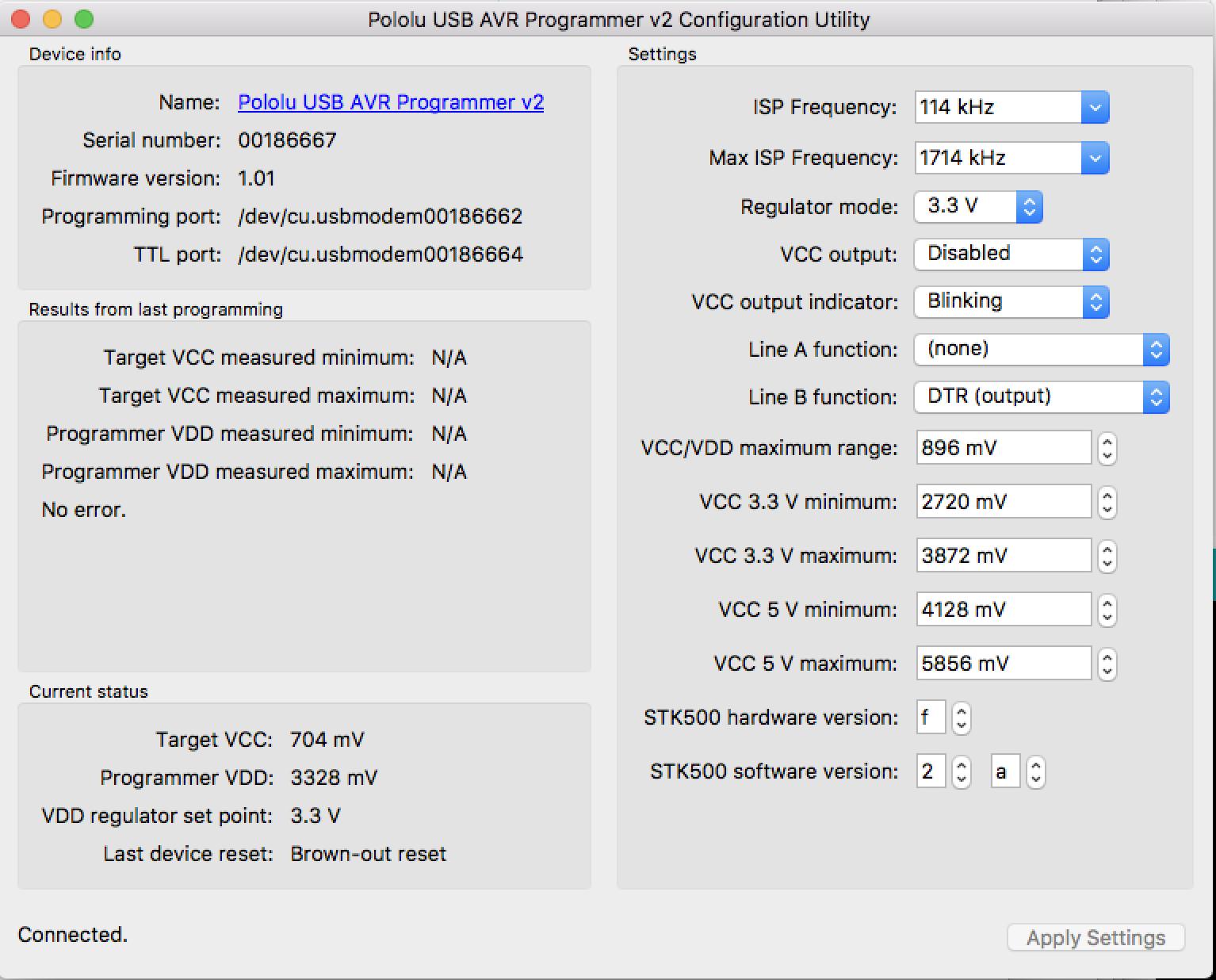
** Pololu AVR V2 Programmer Status**
Target VCC measured Minimum: 832 mV
Target VCC measured Maximum: 832 mV
Programmer VCC measured Minimum: 3328 mV
Programmer VCC measured Maximum: 3328 mV

Regulator Mode: Auto
VCC Output: Disabled

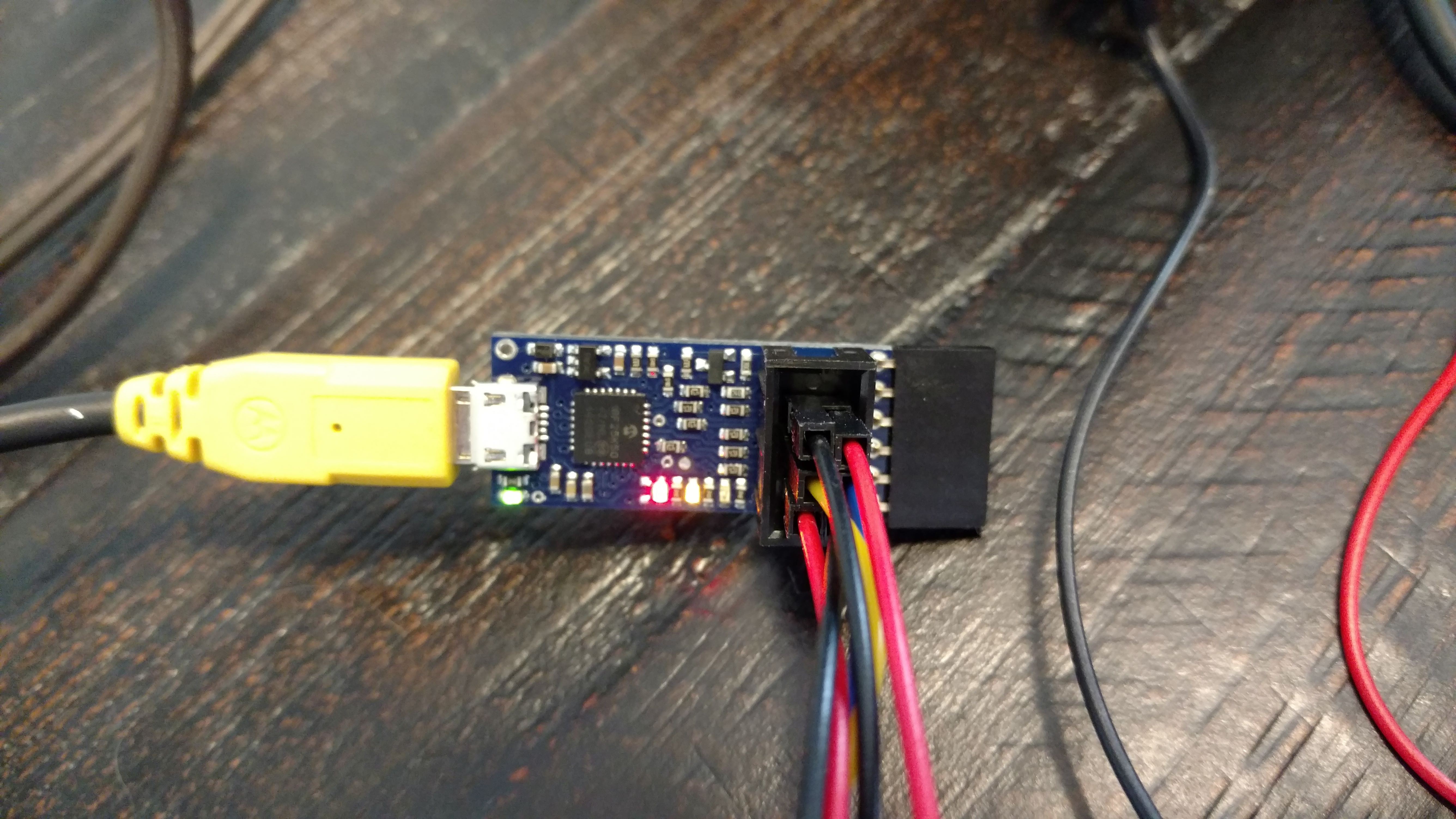
Red light is flashing on programmer approx 1/sec
Green light is on solid
Programming Port: /dev/cu.usbmodem00186662
TTL Port: /dev/cu.usbmodem00186664

Adafruit Trinket Pro Vcc
The schematic for the Adafruit Pro 3v is here:

Configuration:
Mac OSX Sierra v10.12.5
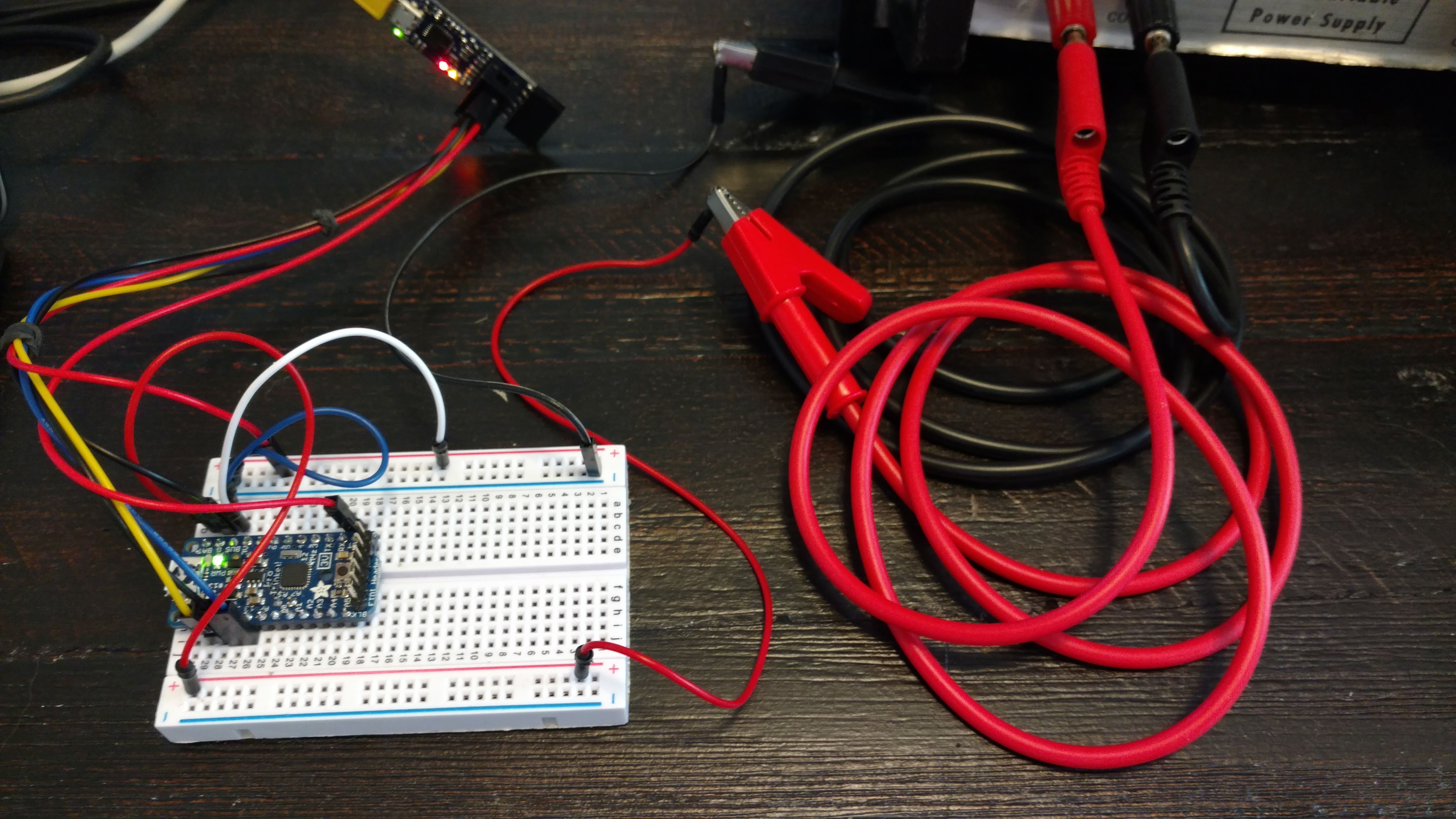
Pololu USB AVR 2 programmer - connected via usb to the FTDI Header of the programmer to the Trinket Pro
Adafruit Trinket Pro 3v - supplied external power of 5.2v of power across the Bat+ and GND pins.
Measures +3.32v at the +3v3 pin

Ports:
ls -al /dev/cu.usb*
crw-rw-rw- 1 root wheel 20, 71 Jun 22 08:28 /dev/cu.usbmodem00186662
crw-rw-rw- 1 root wheel 20, 73 Jun 22 08:27 /dev/cu.usbmodem00186664

Command:

$ avrdude -c avrispv2 -p ATmega328P -P /dev/cu.usbmodem00186662 -v -v

avrdude: Version 6.3, compiled on Sep 17 2016 at 02:19:28
         Copyright (c) 2000-2005 Brian Dean, http://www.bdmicro.com/
         Copyright (c) 2007-2014 Joerg Wunsch

         System wide configuration file is "/usr/local/Cellar/avrdude/6.3/etc/avrdude.conf"
         User configuration file is "/Users/craigdude/.avrduderc"
         User configuration file does not exist or is not a regular file, skipping

         Using Port                    : /dev/cu.usbmodem00186662
         Using Programmer              : avrispv2
         AVR Part                      : ATmega328P
         Chip Erase delay              : 9000 us
         PAGEL                         : PD7
         BS2                           : PC2
         RESET disposition             : dedicated
         RETRY pulse                   : SCK
         serial program mode           : yes
         parallel program mode         : yes
         Timeout                       : 200
         StabDelay                     : 100
         CmdexeDelay                   : 25
         SyncLoops                     : 32
         ByteDelay                     : 0
         PollIndex                     : 3
         PollValue                     : 0x53
         Memory Detail                 :

                                  Block Poll               Page                       Polled
           Memory Type Mode Delay Size  Indx Paged  Size   Size #Pages MinW  MaxW   ReadBack
           ----------- ---- ----- ----- ---- ------ ------ ---- ------ ----- ----- ---------
           eeprom        65    20     4    0 no       1024    4      0  3600  3600 0xff 0xff
           flash         65     6   128    0 yes     32768  128    256  4500  4500 0xff 0xff
           lfuse          0     0     0    0 no          1    0      0  4500  4500 0x00 0x00
           hfuse          0     0     0    0 no          1    0      0  4500  4500 0x00 0x00
           efuse          0     0     0    0 no          1    0      0  4500  4500 0x00 0x00
           lock           0     0     0    0 no          1    0      0  4500  4500 0x00 0x00
           calibration    0     0     0    0 no          1    0      0     0     0 0x00 0x00
           signature      0     0     0    0 no          3    0      0     0     0 0x00 0x00

         Programmer Type : STK500V2
         Description     : Atmel AVR ISP V2
         Programmer Model: STK500
         Hardware Version: 15
         Firmware Version Master : 2.10
         Topcard         : Unknown
         Vtarget         : 0.8 V
         SCK period      : 8.7 us
         Varef           : 0.0 V
         Oscillator      : Off

avrdude: stk500v2_command(): command failed
avrdude: initialization failed, rc=-1
         Double check connections and try again, or use -F to override
         this check.

avrdude done.  Thank you.

Hello.

I moved your post to its own thread since it is a different issue.

I am sorry you are having trouble programming your Adafruit Pro Trinket using the Pololu USB AVR Programmer v2 and thank you for providing so much information about the issue.

It sounds like you are trying to load the bootloader on to your Pro Trinket via its FTDI header, which will not work. FTDI programming (or USB-to-Serial programming) can only update AVRs with a bootloader on them; you will need to use ISP programming to put the bootloader on your Pro Trinket. To set up the wiring for ISP programming, you would need to connect the Pro Trinket’s MISO, MOSI, SCK, RST, 3V, and GND pins to the respective pins on the AVR programmer v2. I recommend reading the “AVR programming” section of the Pololu USB AVR Programmer v2 User’s Guide, especially the “Connecting an AVR for programming” section.

By the way, since you are new to AVR programmers and bootloaders, it might be helpful for you to read this article on Lady Ada’s website to better understand the different types of AVR programming.

Also, is there a particular reason why you are trying to put a bootloader on the Trinket? It usually comes with a pre-loaded bootloader that you could use.

- Amanda

Thank you Amanda!

The links you provided were very useful. I’ve used the content to now solve the issue and successfully loaded the bootloader (using the Pololu USB AVR Programmer). As you suggested, by using the ISP connector with jumpers to the proper pins to the target chip rather than using the FTDI connector it worked. I used the wiring diagram on the link provided. It’s worth mentioning that powering the chip externally on Vcc /Gnd was required as mentioned on that page (in addition to the 6 jumpers on the ISP connector), making a total of 8 breadboard connections on the target board.

I used an Optiboot bootloader which I downloaded from here. I ran “makeall” from the folder: optiboot-master/optiboot/bootloaders/optiboot to compile the full set of bootloaders including “bootloader”.hex file needed for the target board.

One might conclude from this exercise that flashing a bootloader using the FTDI connector isn’t supported, rather flashing a bootloader requires using the ISP connector. However, I’ll yield to experts like yourself on the accuracy of that conclusion as I am no expert.

I was actually targeting a new ATMega88P chip, not the Adafruit board as exercised in the previous entry, but wanted to use the Adafruit as an example because it’s more common and exhibited the same symptoms. The command found to successfully flash the bootloader (from a Mad OSX) was as shown below. I’m not sure the bootloader was properly loaded (it seems too large at 8K in size but that may require more analysis. The command and subsequent output is as follows:

$ avrdude -c stk500v2 -P "/dev/cu.usbmodem00186662" -p atmega88p -U flash:w:optiboot_atmega88.hex:i 

avrdude: AVR device initialized and ready to accept instructions

Reading | ################################################## | 100% 0.00s

avrdude: Device signature = 0x1e930f (probably m88p)
avrdude: NOTE: "flash" memory has been specified, an erase cycle will be performed
         To disable this feature, specify the -D option.
avrdude: erasing chip
avrdude: reading input file "optiboot_atmega88.hex"
avrdude: writing flash (8192 bytes):

Writing | ################################################## | 100% 0.00s

avrdude: 8192 bytes of flash written
avrdude: verifying flash memory against optiboot_atmega88.hex:
avrdude: load data flash data from input file optiboot_atmega88.hex:
avrdude: input file optiboot_atmega88.hex contains 8192 bytes
avrdude: reading on-chip flash data:

Reading | ################################################## | 100% 0.00s

avrdude: verifying ...
avrdude: 8192 bytes of flash verified

When I connect an LED to pin 13, it flashes 3 times in a loop which I understand from reading other blogs indicates the bootloader is successfully loaded.

However, I’m now unable to load the Blink sketch (using the Adruino software) onto the board using the same ISP connector. I’ve also tried the FTDI connector. Both give the same message as shown below.

I’m unclear as to which “programmer” should I be using for the Pololu USB AVR Programmer2 within the Arduino program. Can you share your thoughts? If you have any thoughts on the issue, they would be greatly appreciated. Thank you again for the help.

Output from the Arduino app;

"/Volumes/Code/buildpath/sketch/Blink.ino.cpp" -o "/Volumes/Code/buildpath/sketch/Blink.ino.cpp.o"
Compiling libraries...
Compiling core...
Using precompiled core
Linking everything together...
"/Users/craigdude/Library/Arduino15/packages/arduino/tools/avr-gcc/4.9.2-atmel3.5.4-arduino2/bin/avr-gcc"  -Os -g -flto -fuse-linker-plugin -Wl,--gc-sections -mmcu=atmega88p  -o "/Volumes/Code/buildpath/Blink.ino.elf" "/Volumes/Code/buildpath/sketch/Blink.ino.cpp.o" "/Volumes/Code/buildpath/../../../var/folders/f5/g7ts_mn57mlfmvtbc6y3r6080000gn/T/arduino_cache_95365/core/core_diy_atmega8_series_avr_atmega88_diy_version_atmega88p,boot_optiboot,clock_8MHz,lto_enable_75ec30158253a5e35ff910a671a72404.a" "-L/Volumes/Code/buildpath" -lm
"/Users/craigdude/Library/Arduino15/packages/arduino/tools/avr-gcc/4.9.2-atmel3.5.4-arduino2/bin/avr-objcopy" -O ihex -j .eeprom --set-section-flags=.eeprom=alloc,load --no-change-warnings --change-section-lma .eeprom=0  "/Volumes/Code/buildpath/Blink.ino.elf" "/Volumes/Code/buildpath/Blink.ino.eep"
"/Users/craigdude/Library/Arduino15/packages/arduino/tools/avr-gcc/4.9.2-atmel3.5.4-arduino2/bin/avr-objcopy" -O ihex -R .eeprom  "/Volumes/Code/buildpath/Blink.ino.elf" "/Volumes/Code/buildpath/Blink.ino.hex"
Sketch uses 856 bytes (11%) of program storage space. Maximum is 7680 bytes.
Global variables use 9 bytes of dynamic memory.
/Users/craigdude/Library/Arduino15/packages/arduino/tools/avrdude/6.3.0-arduino9/bin/avrdude -C/Users/craigdude/Library/Arduino15/packages/arduino/tools/avrdude/6.3.0-arduino9/etc/avrdude.conf -v -patmega88p -carduino -P/dev/cu.usbmodem00186662 -b57600 -D -Uflash:w:/Volumes/Code/buildpath/Blink.ino.hex:i 

avrdude: Version 6.3, compiled on Jan 17 2017 at 12:01:35
         Copyright (c) 2000-2005 Brian Dean, http://www.bdmicro.com/
         Copyright (c) 2007-2014 Joerg Wunsch

         System wide configuration file is "/Users/craigdude/Library/Arduino15/packages/arduino/tools/avrdude/6.3.0-arduino9/etc/avrdude.conf"
         User configuration file is "/Users/craigdude/.avrduderc"
         User configuration file does not exist or is not a regular file, skipping

         Using Port                    : /dev/cu.usbmodem00186662
         Using Programmer              : arduino
         Overriding Baud Rate          : 57600
avrdude: stk500_recv(): programmer is not responding
avrdude: stk500_getsync() attempt 1 of 10: not in sync: resp=0x00
avrdude: stk500_recv(): programmer is not responding
avrdude: stk500_getsync() attempt 2 of 10: not in sync: resp=0x00
avrdude: stk500_recv(): programmer is not responding
avrdude: stk500_getsync() attempt 3 of 10: not in sync: resp=0x00
avrdude: stk500_recv(): programmer is not responding
avrdude: stk500_getsync() attempt 4 of 10: not in sync: resp=0x00
avrdude: stk500_recv(): programmer is not responding
avrdude: stk500_getsync() attempt 5 of 10: not in sync: resp=0x00
avrdude: stk500_recv(): programmer is not responding
avrdude: stk500_getsync() attempt 6 of 10: not in sync: resp=0x00
avrdude: stk500_recv(): programmer is not responding
avrdude: stk500_getsync() attempt 7 of 10: not in sync: resp=0x00
avrdude: stk500_recv(): programmer is not responding
avrdude: stk500_getsync() attempt 8 of 10: not in sync: resp=0x00
avrdude: stk500_recv(): programmer is not responding
avrdude: stk500_getsync() attempt 9 of 10: not in sync: resp=0x00
avrdude: stk500_recv(): programmer is not responding
avrdude: stk500_getsync() attempt 10 of 10: not in sync: resp=0x00

avrdude done.  Thank you.

Problem uploading to board. See http://www.arduino.cc/en/Guide/Troubleshooting#upload for suggestions.

When I select the Atmel Stk500 development board, the sketch loads (using the USB AVR Programmer v2) via the USB port, connected in the ISP configuration. However, I’m still searching for an answer for using the FTDI connector.

From the Arduino IDE output, it looks like you are using the Programming Port to upload your sketch. You need to use the TTL Serial Port (/dev/cu.usbmodem00186664).

Just in case you have not already seen, it might be helpful for you to read the “Connecting to a serial bootloader” section in the user’s guide for the AVR programmer v2. That section of the guide explains how the programmer’s USB-to-serial adapter uploads a sketch onto a board (with a bootloader) through the Arduino IDE.

- Amanda

Amanda:

Thanks for your reply.

I’ve read the link you suggested, and changed the port, but I’m not seeing a change. I have a bootloader loaded, BTW.

When I connect the Pololu programmer V2 FTDI port to my board, (which is wired to the ATMega88P chip the same as the Tinket Pro 3v) , I’m not seeing on the Pololu AVR2 programmer output that I would expect. That is, Target VCC is 0V. When I try to Enable VCC output at either 3.3v or 5v I get “The connection to the device was lost” and the red light starts blinking. Is that expected? I would think I should see the Target VCC at non-zero. However, I have an LED light on pin 13 of the target board, it’s green indicating my board has power.

Any thoughts appreciated.

Craig

Hi, Craig.

It sounds like your programmer might have experienced a brown-out reset when you set VCC to be an output. After a brown-out reset occurs, the programmer blinks its red LED four times while leaving the yellow LED off. For more information, I suggest reading the “LED feedback” section and the “Using VCC or VBUS to supply power” section of the AVR programmer user’s guide.

Was your board externally powered at the same time when the programmer’s VCC pin was set to output? When the VCC is in output mode, you should not connect it to the output of another device since it will create a short between the two boards.

Can you post pictures showing how you have everything connected between the AVR programmer and your ATmega88P board? Also, what power supply are you using to power your ATmega88P board?

- Amanda

Thanks for the reply, Amanda.

The board wasn’t externally powered when connected to the Programmer. The state of the LEDs is the Programmer RED LED is flashing about 2 times per second (not 4 times). The other LEDs are off.

The photo would be hard to interpret, but I have it wired with jumpers between the Pololu USB AVR Programmer and the Adafruit Pro 3v Trinket board as follows:

Programmer . Adafruit Pro Trinket 3V
Pololu . Board


RST . - RST
G - G
SCK - 13
MOSI - 11
MISO . - 12
VCC - BAT+

I also tried:
VCC . - BUS
Same result.

Any thoughts appreciated.

BTW, the same configuration is used for either my target ATMega88P or the Adafruit board. And the same result applies (red light flashes quickly, and the software disconnects from the board. BTW, I’m using a Mac OSX Sierra MacBook Pro 10.12.5 computer.

The power supply used (when not trying to power it from the Pololu programmer) is dual variable power supply set it to 3.3v.

It sounds like you might have set the programmer’s VCC pin to be an output and connected it to the Trinket’s BAT+ pin. The BAT+ pin has a 10 uF capacitor on it. That capacitance is high enough that it will probably cause a brown-out reset when the programmer enables its VCC output, so that might explain the brownout reset that is reported in your screenshot of the programmer’s configuration utility.

It sounds like you also tried connecting the AVR programmer’s VCC pin to the Trinket’s BUS pin. According to its guide on the Adafruit website, the BUS pin is connected directly to the USB cable’s 5V power supply line and is solely used as an output pin. You should NOT use that connection with the programmer’s VCC pin set to output mode.

If you still cannot load sketches with the FTDI header, there are some more things you could do to troubleshoot. You should disable the programmer’s VCC output and make sure the trinket is powered properly from your power supply. You should remove the six wires from the ISP interface just in case they are causing an issue. Those connections look fine to me, but it is generally a good idea to simplify your system when debugging.

If that does not help, can you post pictures showing exactly what your connections are for that setup? The pictures should show how you have the programmer connected to the Trinket’s FTDI header pins. Also, please let us know what the LEDs on the programmer are doing, post the verbose output from the Arduino IDE, and post a screenshot of the configuration utility after the failed programming attempt.

- Amanda