I am using an QTR-MD-04A Reflectance Sensor Array at 3.3V to detect a line for a small line following robot. Unfortunately I am only getting a 2% variation (of the 0V - 3.3V range) in output value with line compared to without.
For these tests the sensor was 3-4mm above a piece of white printer paper with a black area created using a sharpie.
I have used both a microcontroller and multimeter to read the output, though on the microcontroller the noise outweighs the variation to a large degree.
The product is listed at operating between 2.9-5V, so I assume I have overlooked something…
That sensor should work with 3.3V. Are you using one of our Arduino examples? Can you post a sample of the output you are seeing? Can you also post pictures that show how everything is connected and the paper you are using to test?
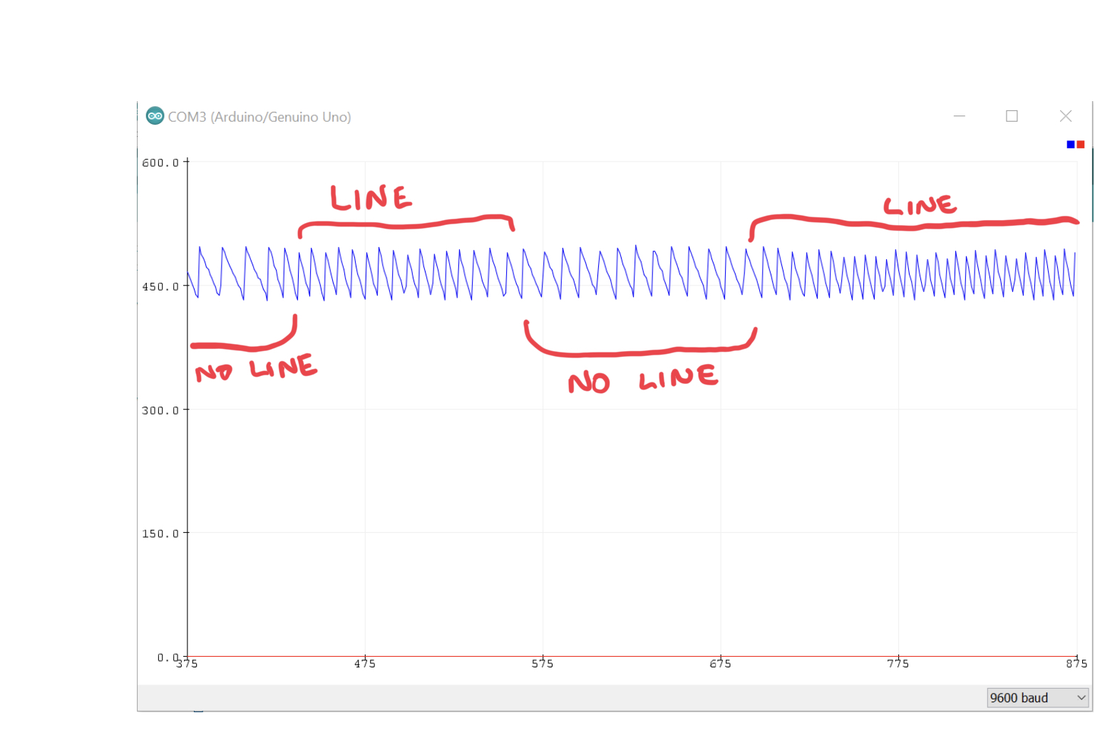
I switched to a 5V Arduino Uno to (hopefully) make things simpler:
I tried the sample code, but did not get any meaningful calibration readings, so only got readings of 0. Because of this, I reverted to using the analog in serial out example code on the arduino app.
It is hard to see what pins on the sensor you are connecting to in that picture. Could you post a diagram of your connections or list the connections between the sensor and Arduino? Could you also post a picture of the component side of your board?
Late night soldering… never a good idea. I had the CTRL pin hooked to Vcc, and no Vcc.
In case anyone is looking do use 3V and wondering if it works - it does.
I have been able to get a good reading at 10-12mm from a surface, with an output between 0.24V - 0.86V w/ and w/o line, a very usable range.