I’d like to build a small robot using your 42/19mm wheel and encoder set but I’m not clear on a couple of (mechanical) things:
Is the encoder board designed to fit on one side of a chassis (like your RRC01A) and the bracket on the other side (using the same mounting screws)?
How do I choose a pair of motors to work with these wheels (I’d like something that will run max 10 rev/sec with your TB6612FNG dual motor driver)? Is the #995 250:1 micro metal gearmotor a good fit? Do I need a separate plate to connect it to the wheel?
Are these wheels/brackets/motor combinations compatible with your RRC01A chassis – will it all fit together?
The bracket and encoder must be on the same side of the chassis.
The best way to choose a pair of motors is to look at our motor comparison page. #995 will work with the wheel encoder set but it has a max RPM of 120 at 6V which is less than you wanted. If you want 10 rev/sec (600 rev/minute), you might want to go with #998 (50:1 HP) which has a max RPM of 630 at 6V.
The RRC01a chassis is not compatible with the wheel encoder set. A laser-cut chassis that is compatible with the wheel encoder set is on our list of things to do. In the meantime, you could use our custom lasercutting service to cut your own. I can send you a Corel Draw file as a starting point if you are interested.
Thanks for your prompt reply. A couple of related questions:
To mount the motor/encoder on the chassis do you just put the encoder board underneath the motor bracket and motor? That sounds straightforward.
Would the 42x19 wheels and a pair of #998 motors/brackets fit on the RRC01a chassis if I cut the wheel holes bigger and possibly use mounting holes I drill out myself? I don’t mind some rework to the chassis if it’s large enough to accommodate the motors and wheels (and a castor ball).
And it looks like the 42x19 wheels don’t need a separate mounting plate to attach to the #998 motor – is that right? I would just need the wheel/encoder kit and the motors – does the hardware to connect wheels to motors come with the motors or the wheel/encoder kit?
Yes, you mount the encoder board between the bracket and the chassis.
I just looked at RRC01A and an encoder set and I don’t think reworking it is worth it. If you don’t want to laser cut a custom chassis, you could try to use a piece of wood, PVC or styrene, and cut your own chassis.
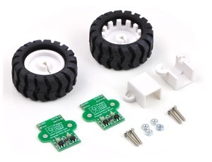
The wheel hub press fits onto the shaft of the motor so it doesn’t need any special mounting plates or hardware. The encoder kit comes with the hardware shown in the picture below, which is used to mount the bracket, motor, and encoder to the chassis.
I thought you might like to know that the chassis we said was on our list of things to do is done and it is available for purchase. It is the Pololu 5" robot chassis RRC04A. It is designed around our micro metal gearmotors, 42mm wheels, and encoders, so it probably is a good fit for what you want to do.
The extended brackets, included with the wheel and encoder set, work with the nuts that come with them. The nuts are for #2-56 screws (the ones that come with the set are #2-56) and the nuts are 3/16" in width and 1/16" in height. You might also find the extended bracket page helpful because it has a mechanical drawing of the bracket on it.
I am playing with my encoders and wanted to know if they are working properly. I attached them to my chassis, turned on the motors and powered the encoders using logical Vdd. I have not seen, however, a digital output. All I’m getting is a positive 5 V for both output A and output B. It there any quick and dirty test to know if my encoders are working. I haven’t noticed a pwr on/pwr off lcd.
Do you have the wheels on? Even without wheels, you should be able to bring something reflective (even your finger could be enough) close to the sensors to make the outputs change.
Also, I don’t understand what you mean by “pwr on/pwr off lcd”.
I figured out that my wheel/encoders are working. However, I’ve had to modify the motor / encoder / bracket alignment. I pushed the encoder and bracket closer to the wheel. That way the encoder ir leds are closer to the wheels ridges. Another interesting modification I played with is to leave the alignment normal, but include a reflective LED. The LED is positioned to shine light onto the wheel ridges.
I looked at the picture carefully of the wheel and encoder and bracket. I also noticed that my motors fit perfects inside the brackets. Inside the brackets, the molding is made to complement the wheels nicely. But, I also think that the system should work as is without these modifications. Perhaps I am doing something incorrectly.