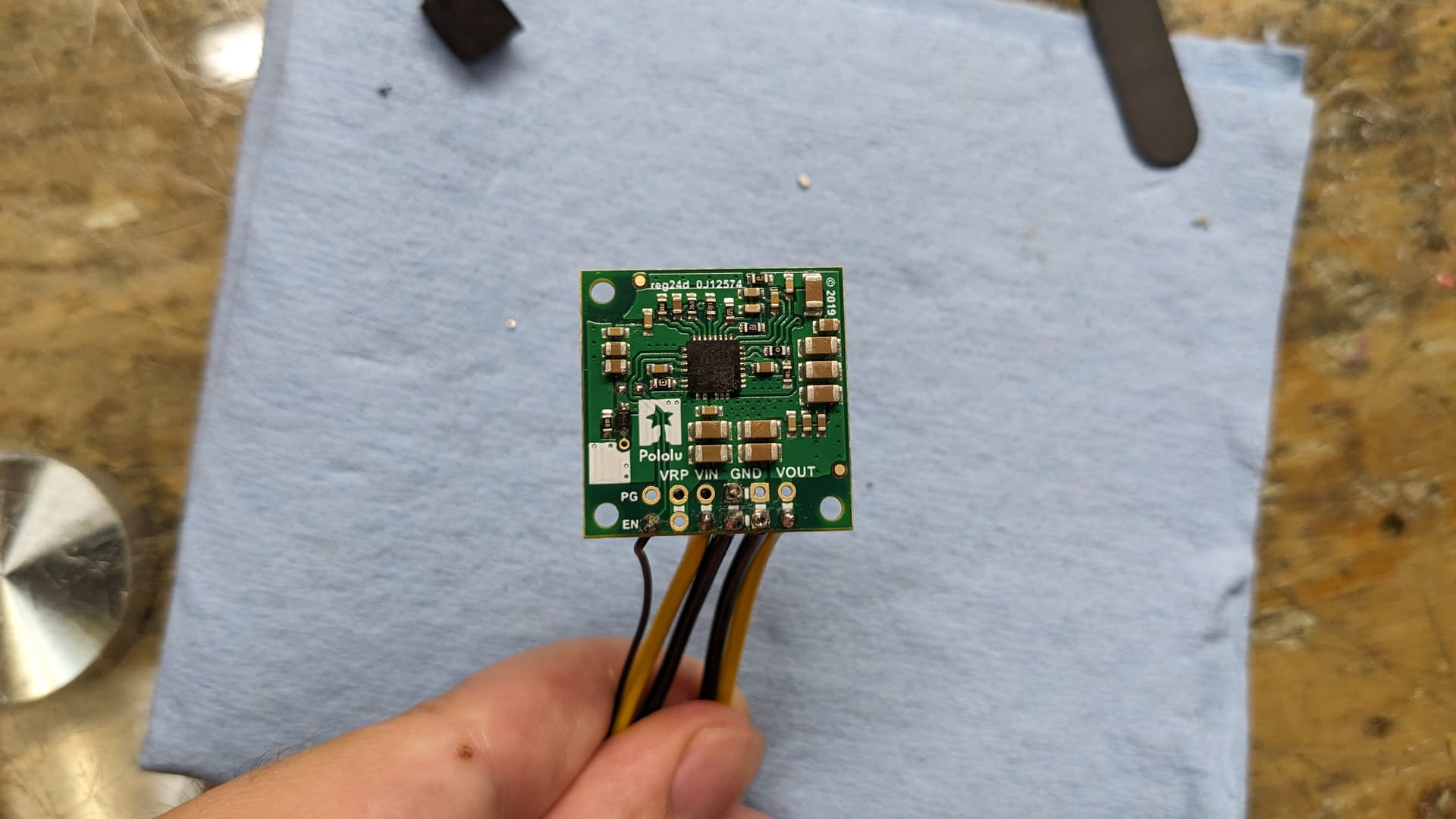
I will be using a 12V, 4.5A Step-Down Voltage Regulator D36V50F12 to step down 19v to 12v to power a GPU.
I already have a module that allows me to sync the power of the GPU to when the Minipc is turned on, but I was wondering if the EN pin on the D36V50F12 could play the same purpose?
The EN pin will be connected to a pin on the minipc board that provides 3.3V. So when I turn on the PC, the 3.3V enables the EN, allowing the VOUT to output 12V. And when I turn off the pc, the voltage would drop to 0V to the EN, which would close the VOUT.
Am I understanding that right? Would that work? Thanks
As mentioned on the product page, the #4095 D36V50F12 regulator has a 100k pull-up resistor between the EN and VIN pins, so if you want to use the EN pin as you described, you would likely want to remove this pull-up resistor and add an external pull-down resistor instead.
I have indicated the pull-up resistor with the red outline in the following picture:
I am not familiar with the timing and tolerances required in a mini PC setup like that, but you might consider double checking the behavior of that 3.3V pin on your mini PC during startup and shutdown to make sure it doesn’t do anything erratic and functions how you expect.
Hi, thank you for your answer. However, I am not well versed in resistors. To be able to pull down then, can I remove this resistors, and then with wires connect it to the EN trace and the ground to make it a pull-down resistor?
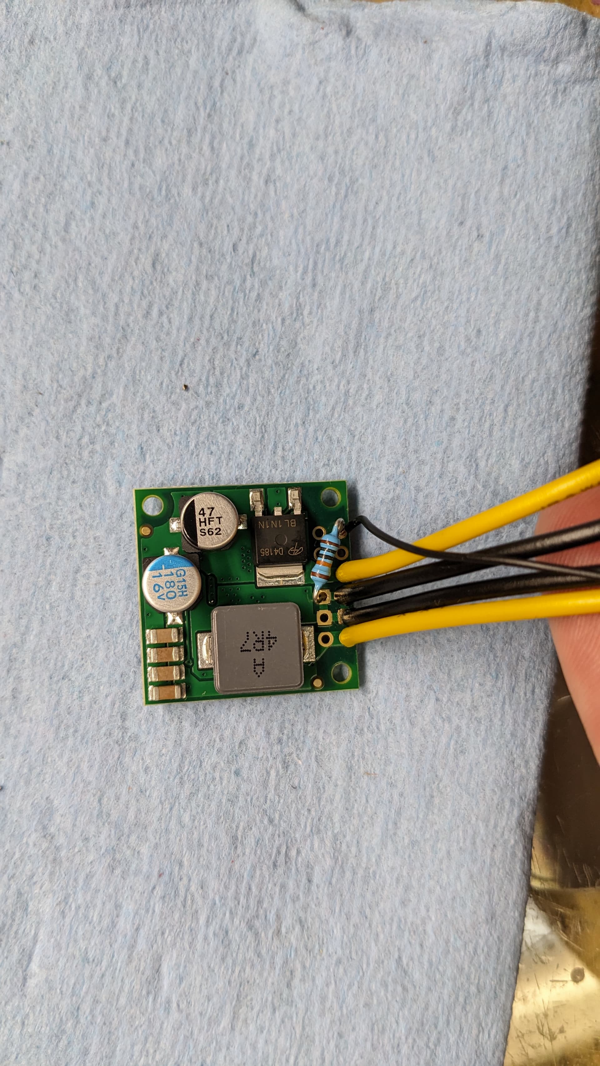
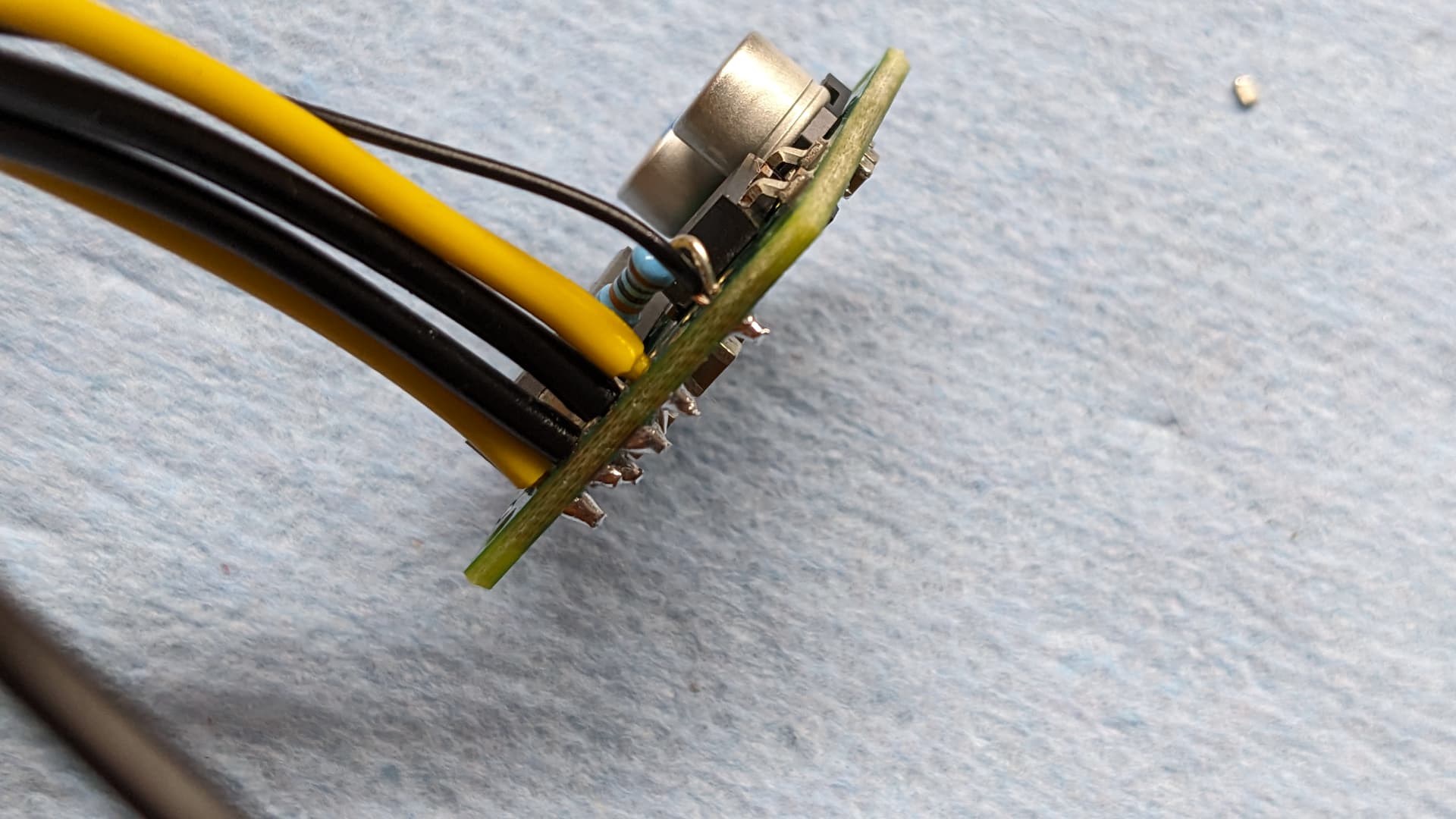
After removing the indicated surface-mount resistor, you can add your own through-hole resistor between the EN pin and one of the GND pins to pull it down. Something in the 100kΩ range should be fine.
If you do not feel comfortable removing the surface-mount resistor without damaging the board, you could also use a stronger pull-down resistor to simply overpower it instead. The down-side of this approach is that it would waste more power. What resistance is necessary to overpower the pull-up resistor would depend on your operating voltage (since the pull-up is connected to VIN), but something around 1kΩ should handle it.
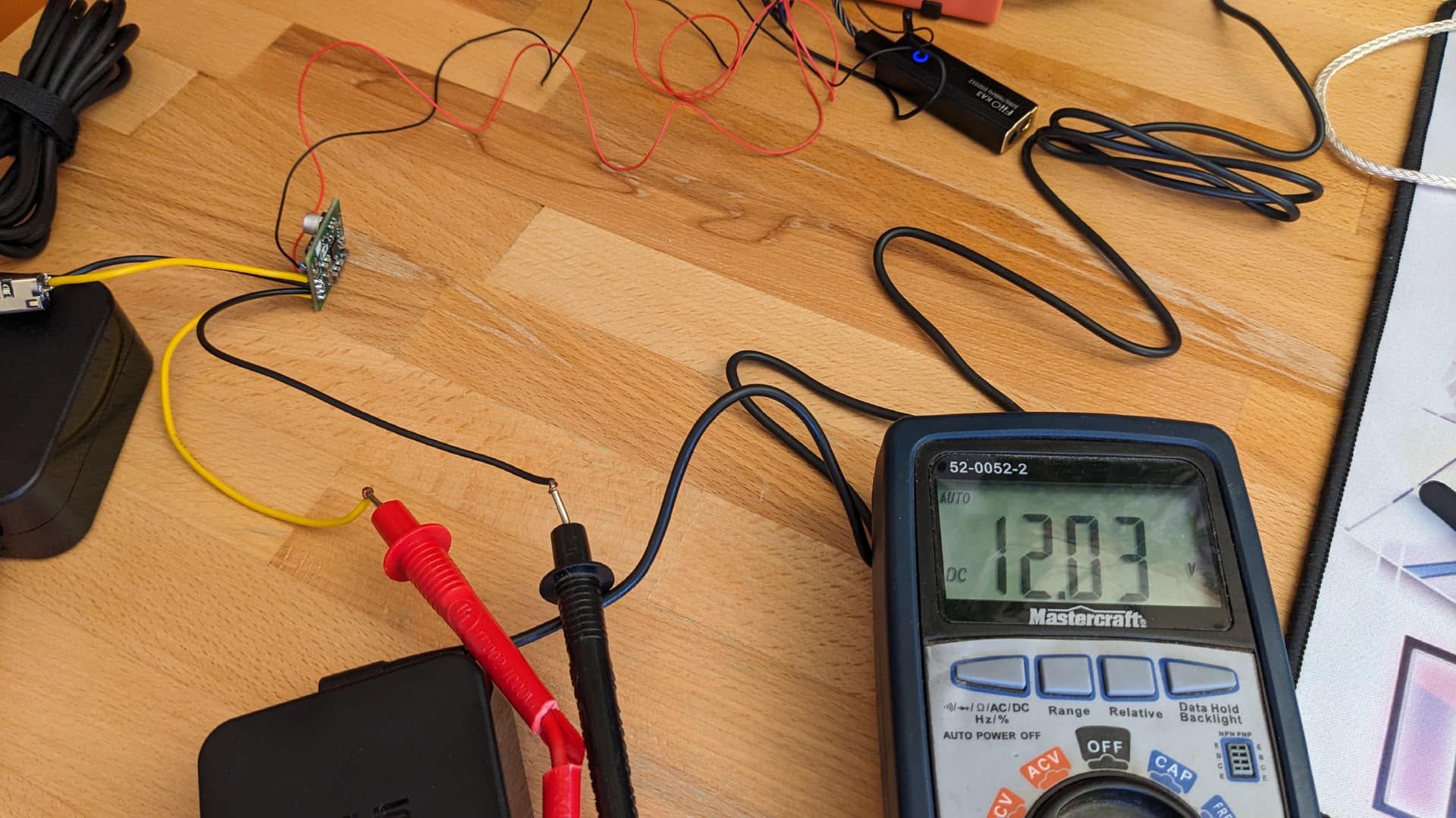
I have an issue and I want to know what I could have done wrong. I followed the indication above, but when I’m testing I do not get any voltage from the VOUT with my multimeter.
Sometime when I turn on the motherboard, with the EN pin connected to a pin on the motherboard which outputs 5V all the time, I get a small transient spike up to 1V that then gradually returns to 0V.
My source outputs is a constant 19.5V, so I suppose it might be a soldering issue that I don’t see? Here’s picture of my soldering job to see if I’ve done any mistake. Thanks
To the best I can tell from your pictures, your modification to the board looks okay. (Though I do not especially like the choice of using a black wire for EN, but it is inconsequential as long as it gets connected to the right place.)
What voltage do you measure on EN when you have it connected to the 5V output, and just to make sure, do you have a common ground connection between the motherboard and the regulator? Can you confirm that the pin on your motherboard still outputs 5V if you disconnect it from EN? Does the regulator turn on and behave as expected if you connect EN to VIN?
Yes! Thanks! That was my issue! I totally forgot I had no more common ground between the two as I was using distinct power adapters. Adding a cable that connect to the ground pin on the motherboard, alongside the 5v cable for EN, solve the issue.
(Also note for other users, but I was still powering my powering my motherboard with a 12V power adapter. Powered this way, it didn’t yield any result. Only when I powered my motherboard with his original 19V power adapter that the pull-down worked, with the converter outputting 12V)
Ya I know it’s not the right colour norm. It was the first thin cable that came under my hand. I should not tell you that I used a red cable for the common ground.