
Hello,
I’ve recently purchased a USB AVR programmer V2.1 and succesfully flashed an ATMEGA168, following the instructions of the User’s Guide in section 5.5 AVR programming using AVRDUDE.
I’ve made a tiny circuit on a breadboard, with the micro, a led controlled by the code, etc. and everything worked fine, using the pin VCC of the programmer enabled to 3.3 volts.
As far as I understand, (please correct me if I’m wrong), it should be also possible to flash the micro with the pin VCC output disabled and powering the circuit with batteries or a external power supply. Is that correct?.
I’m trying to do that, i.e. trying to flash again the same code on the same circuit, but powering the circuit with my own power supply instead of powering with pins VCC and GND from the programmer, but I cannot do it. I get an error message from AVRDUDE and also a weird message in the configuration software of the programmer (pavr2gui) when I open it after trying to flash.
I get the following messages:
-
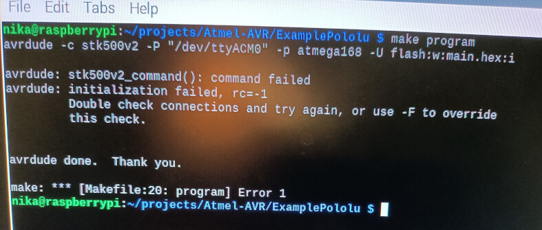
From AVRDUDE:
avrdude: stk500v2_command(): command failed
avrdude: initialization failed, rc=-1
Double check the connections and try again, or use -F to override this check. -
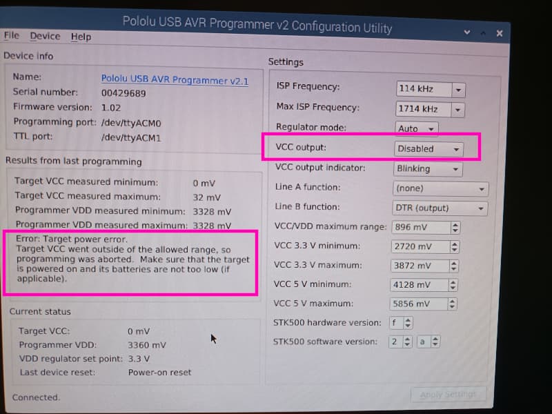
From pavr2gui
Error: Target power error.
Target VCC went outside of the allowed range, so programming was aborted.
Make sure that the target is powered on and its batteries are not too low (if applicable)
I can attach some photos of these messages:
I’ve tried to look for details in the User’s guide about flahsing with VCC disabled and self-powered circuits but I’ve not found any detail, so tried my own method (probably wrong method). I’ll explain what I did below:
- Disabled VCC pin with pavr2gui
- Disconnected VCC pin from the power rail of the breadboard
- Setup an external supply to 3.3 volts and verified the voltage with a multimeter → 3.283volts.
- Connected the positive output of the power supply to the breadboard, where the VCC pin was before.
- Connected the negative output of the power supply to the breadboard, replacing GND pin of the programmer
- Switched the power on
7.Tried to flash…and failed.
I’ve also tried to connect the negative output of the power supply to the GND pin together in the breadboard (to make both the same ground reference level?)… Excuse me if it’s stupid, but I’m a rookie with electronics, but the results were also bad…no flashing.
I think there is no problem on the circuit, as I can flash it and make your code work, but ONLY if I enable the VCC output. I cannot make any flashing if I disable the VCC output with the configuration utility.
I can send photos and/or diagram of the circuit if it helps, although I think the problem is “myself” ![]() . Something I’m missing or not understanding correctly.
. Something I’m missing or not understanding correctly.
I will appreciate any help on this issue,
Thank you,
Pablo