Hi,
Can anyone advise on how the Line A & Line B functions should be set?
I have tried various combinations but can’t get the Auto Bootloader to work.
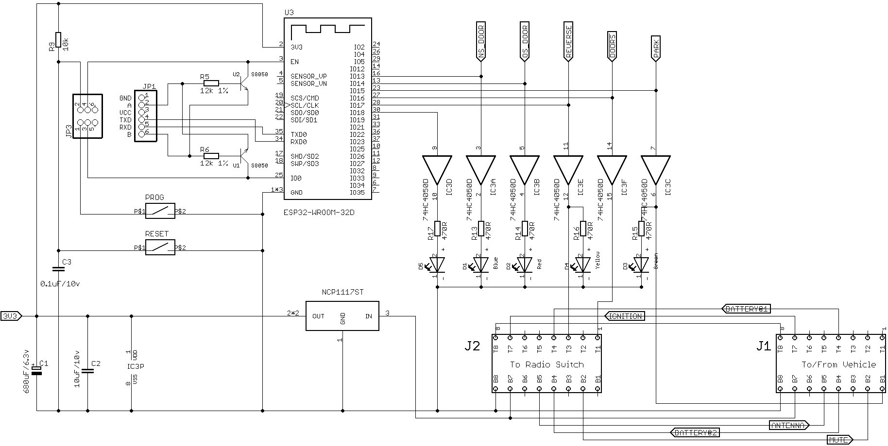
This is the circuit (I hope! But I can’t see how to preview…)
Regards,
Hi,
Can anyone advise on how the Line A & Line B functions should be set?
I have tried various combinations but can’t get the Auto Bootloader to work.
This is the circuit (I hope! But I can’t see how to preview…)
Regards,
Opps,
I think I should have mentioned that I am using the the Arduinio IDE.
Hello.
What happens when you try setting Line A and Line B set to DTR and RTS to match the labels in the schematic? Can you post more details about the ESP32 board including a full schematic?
-Nathan
Hi Nathan,
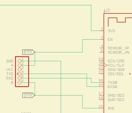
… which to what? I am assuming Line A & B are outputs. So Line A could be set via the v2 Configuration Utility as “DTR (output)” or “DTR reset (output)” or “RTS (output)”. The same would apply to Line B.
Trying some (of the 27) possibilities gives the dreaded "Connecting …------…------… " Connection error.
And here is my schematic:
Regards, ~M
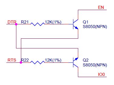
Yes, Line A and Line B are outputs that can be set to different functions. We are not entirely familiar with the automatic bootloader functionality of ESP32 boards, but this documentation on GitHub makes it seem like the EN and GPIO0 pins should be connected directly to pins with RTS and DTR outputs respectively. It is unclear to me what the NPN transistors in your circuit are doing.
You probably want to use the DTR (output) and RTS (output) modes for the output lines of the AVR programmer, but you can look at the Serial control lines section of the programmer’s users guide for more information about the signal sent by DTR (output) and DTR reset (output) pin modes. There are some notes on that GitHub page I mentioned about how the ESP expects DTR and RTS pins to be toggled.
-Nathan
Resolved.
The problem here is “old” internet postings! Although, I had been using ![]() official Espressif documentation, it seems that the silicone has been updated and the “Auto Bootloader” circuitry (crossed transistors - shown at head of thread) is now NOT necessary.
official Espressif documentation, it seems that the silicone has been updated and the “Auto Bootloader” circuitry (crossed transistors - shown at head of thread) is now NOT necessary.
Can’t show timings (don’t have a DSO), but this working for me:
Pololu Programmer v2.2    << == >> ESP32
Pin A set as RTS (output) << == >> EN (pin 3)
Pin B set as DTR (output) << == >> GPIO0 (pin 25)
TXD                       << == >> RXD (pin 34)
RXD                       << == >> TXD (pin 35)
Regards,
I’ve been trying to flash a ESP-12F controller using the above diagram, a simple flash sketch just to test the theory, however the Pololu can’t seem to connect to the board.
RTS (output) on pin A
DTR (output) on pin B
Connecting…………………_
esptool.FatalError: Failed to connect to ESP8266: Timed out waiting for packet header
esptool.FatalError: Failed to connect to ESP8266: Timed out waiting for packet header
Any advice would be most welcome!
Hi,
While the above worked in my “limited” situation, you may get better mileage by having a look at this:
FTDI wrapper for esptool
And these are lines (truncated to end of line) 100, 102 & 104 of my
~/.arduino15/packages/esp32/hardware/esp32/1.0.4/platform.txt.
Note: Linux path.
line 100 - tools.esptool_py.upload.pattern="{path}/{cmd}" --chip esp32
line 102 - tools.esptool_py.upload.pattern.linux=python "{path}/esptool-ftdi.py" "{path}/{cmd}" --chip esp32
line 104 - #tools.esptool_py.upload.pattern.linux=python "{path}/{cmd}" --chip esp32
Which is, Copy and rem out the existing upload pattern. Then add the path to the esptool-ftdi.py wrapper at the beginning of the line copied.
Lastly add the esptool-ftdi.py file to the same location (~/.arduino15/packages/esp32/tools/esptool_py/2.6.1/), alongside the esptool.py.
Hope this helps, M.
I’ll take a look. Thanks for the quick reply