Hello,
I’m happily using my USV AVR Programmer 2.1 both to program (ISP) and debug via Serial (sending messages that I can read on my computer).
Everything works fine, but I wanted to send some bytes from the computer to the board using the Serial interface embedded in the Arduino IDE and it looks like the information is not being sent to the board.
I’m powering the board from the programmer’s AVR connector, so I’m only connecting the TX and RX lines of the USB-to-TTL connector.
With the same exact connections, I can read the board outputs, but not write to it. Am I missing something basic?
Thanks a lot!
Eric
Ground must be connected.
Your post is very confusing. What does Serial.write() have to do with sending messages from the PC to the Arduino board?
Please post the code and a complete wiring diagram, showing all the connections between the Arduino, the adapter and the computer. Hand drawn is fine.
Hello Jim, thanks for the reply.
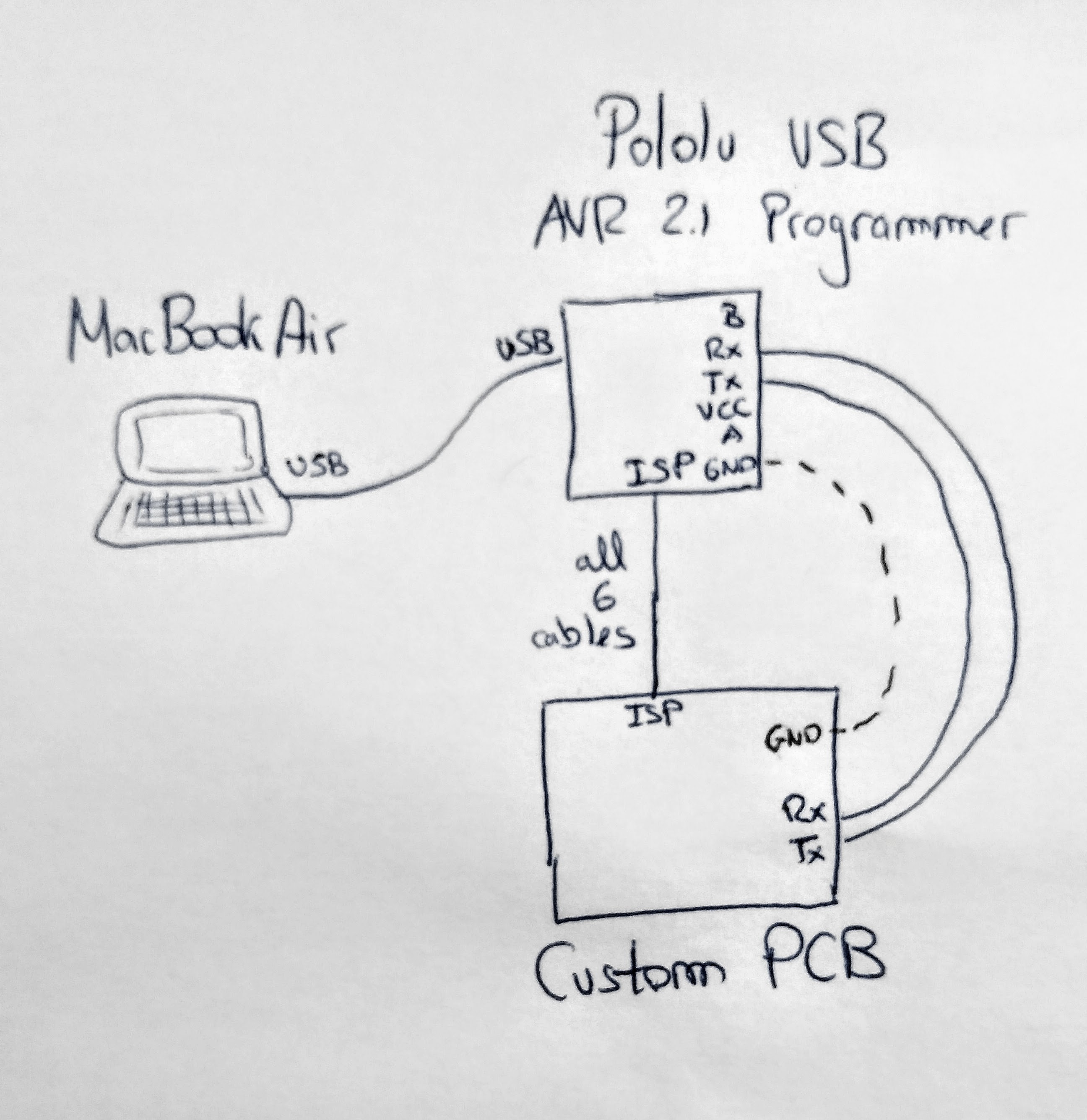
Here is the wiring diagram:
And here the code:
void setup(){
    Serial.begin(9600); // Setup serial for debug purposes
    Serial.println("This is a test");
}

void loop(){
  // send data only when you receive data:
  if (Serial.available() > 0) {
    incomingByte = Serial.read();     // read the incoming byte:
    Serial.print("I received: ");     // say what you got:
    Serial.println(incomingByte, DEC);
  }
}
I can see the Serial.print “This is a test” in the Serial Monitor from Arduino IDE, but when I send data to the board it does not arrive (since the Serial.print “I received” in the if statement does not trigger).
I tried connecting the GND from Pololu’s Serial header to the GND from my board as you suggested, but it did not solve the problem. Note that, since I simultaneously have the ISP connected and the Tx and Rx from Serial, GNDs were already connected anyways.
Is there any difference between sending and receiving messages that would need other pins from Pololu’s Serial header to also be connected (VCC, A, B)?
Thanks a lot for the support!
Nothing obviously wrong with what you posted, but important information was left out.
Which processor is on the custom PCB, and which pin is identified as “TX”?
Have you verified the relevant connectivity, all the way from the chip TX pin to the programmer RX pin?