I just received my 3Pi earlier and have been trying to get it up and running. I got the package so I’m using the Orangutan USB Programmer. I followed the guide to the letter but when I get to the program phase I get the following :
I’m sorry to hear you’re having trouble with your 3pi. Are you using AVR Studio as your programming software? Is your 3pi turned on while you’re trying to program it? Is your 3pi currently running the demo program that was on it when it shipped?
All of those steps sound correct, and if the demo program is running it means the 3pi is alive and functioning. I don’t suppose you have another AVR-based controller board that you could try programming with your Orangutan USB programmer? Is your computer running Windows?
Nope, this is my first time using an AVR. I normally use PICs. I am running Windows XP SP3. Perhaps the Orangutan is malfunctioning? Is there any way to diagnose that without any other boards?
From the symptoms you are describing, it sounds like a problem with the electrical connection between the programmer and the 3pi. Since AVR Studio can connect to the programmer and the 3pi is still running the demo code, it seems like both devices are functioning.
When your programmer is connected to the computer, do you see the green USB led lit? When the 3pi is off or it is disconnected from the 3pi, do you see the red status LED flashing? When it is connected to the 3pi and the 3pi is turned on, does the red LED turn off and stay off?
My hope is that there is a problem with the cable you are using to connect the programmer to the 3pi. Do you have a multimeter? If so, can you use it to perform continuity checks from one side of the ribbon cable to the other on all six conductors? Perhaps even better would be to perform continuity checks from the soldered header pins on the programmer to the soldered header pins on the 3pi with the two connected.
So the header on the cable was connected backwards? If so, I apologize for the defect and am very glad you were able to work around it to get things working!
The socket on the 3pi was installed backwards. Yes I am glad too! I setup a course last night and was able to tune it a little bit more. Going to start my own project soon. Thanks!
I’d like to get to the bottom of the problem a bit further. Can you describe where the notch in the programming header on the 3pi is? Is on the same side as the LCD, or is it facing the outside of the robot?
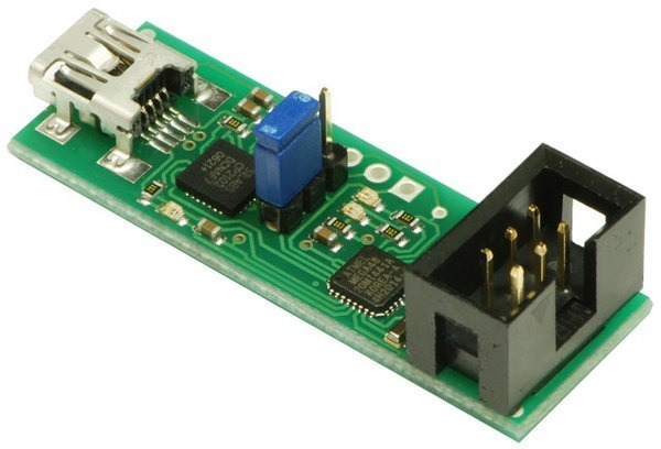
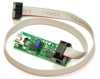
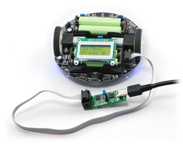
I’m sorry for taking so long to get back to you. Your description of the orientation of the ISP header on the 3pi makes it sound like it’s correct, so your problem must lie with the connector on the programmer or with the cable itself. Can you compare your programmer and cable to the ones in the following pictures:
I think the confusion with the programming header orientation was actually a problem with the 3pi this picture: https://www.pololu.com/picture/thumbnail/0J852.jpg?size=600
It appears the programming connector in that one is actually backwards. Perhaps an old prototype?
The programming header in that picture is oriented correctly. On the Orangutan USB programmer, the connector has its notch and pin-one mark facing outward, aligned with the edge of the PCB. On the 3pi, the connector has its notch and pin-one mark up against the rear battery holder, facing the LCD. Why do you think that it is backwards?
I’m sorry; I was thinking about it backwards. I should have said it would lead one to believe that things were backwards, as the notch in the programming header on the 3pi faces inward while the cable goes outwards; and both the notch and cable face outward from the baby orangutan.
So I guess what I thought was that the orangutan’s cable was in backwards, but even then I was mistaken, so I was wrong twice.
Sorry for the confusion on my part.

