Hello,
I am not able to detect AltIMU-10 v5 as an i2c device with raspberry pi.The connections are as below and I checked them multiple times:
SCL >>5
SDA >>3
GND>>34
Vin>>1
I also use a level shifter to convert 5 v to 3.3v useful for the pins of the raspberry pi.I used the steps from the link below to work with IMU:
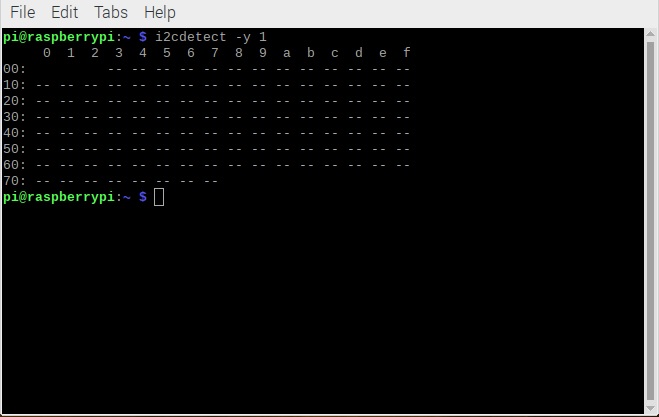
When I run the command below:
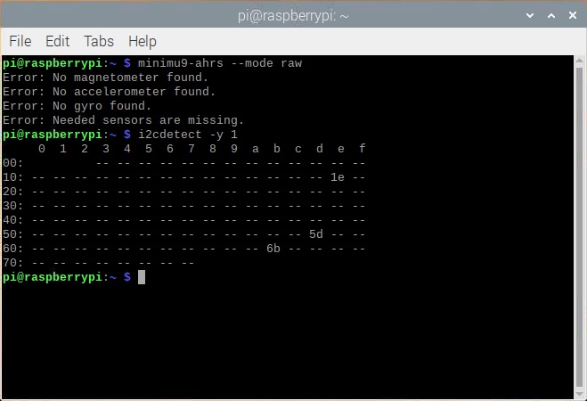
i2cdetect -y 1
I do not see any specific address allocated to IMU.Do you have any idea how I can solve this problem?
I guess the problem is not from i2c itself as you can see in the picture below:
Hello. I’m sorry you are having trouble connecting your AltIMU-10 v5 to a Raspberry Pi.
Your connections sound good, but it is not clear if you are using a level shifter between the AltIMU-10 and the Raspberry Pi. You should not need an external level shifter for the AltIMU-10 (it already includes on-board level shifters) so I recommend taking it out of your system if you can. Furthermore, I recommend simplifying your system as much as possible and removing any components not needed to demonstrate the problem.
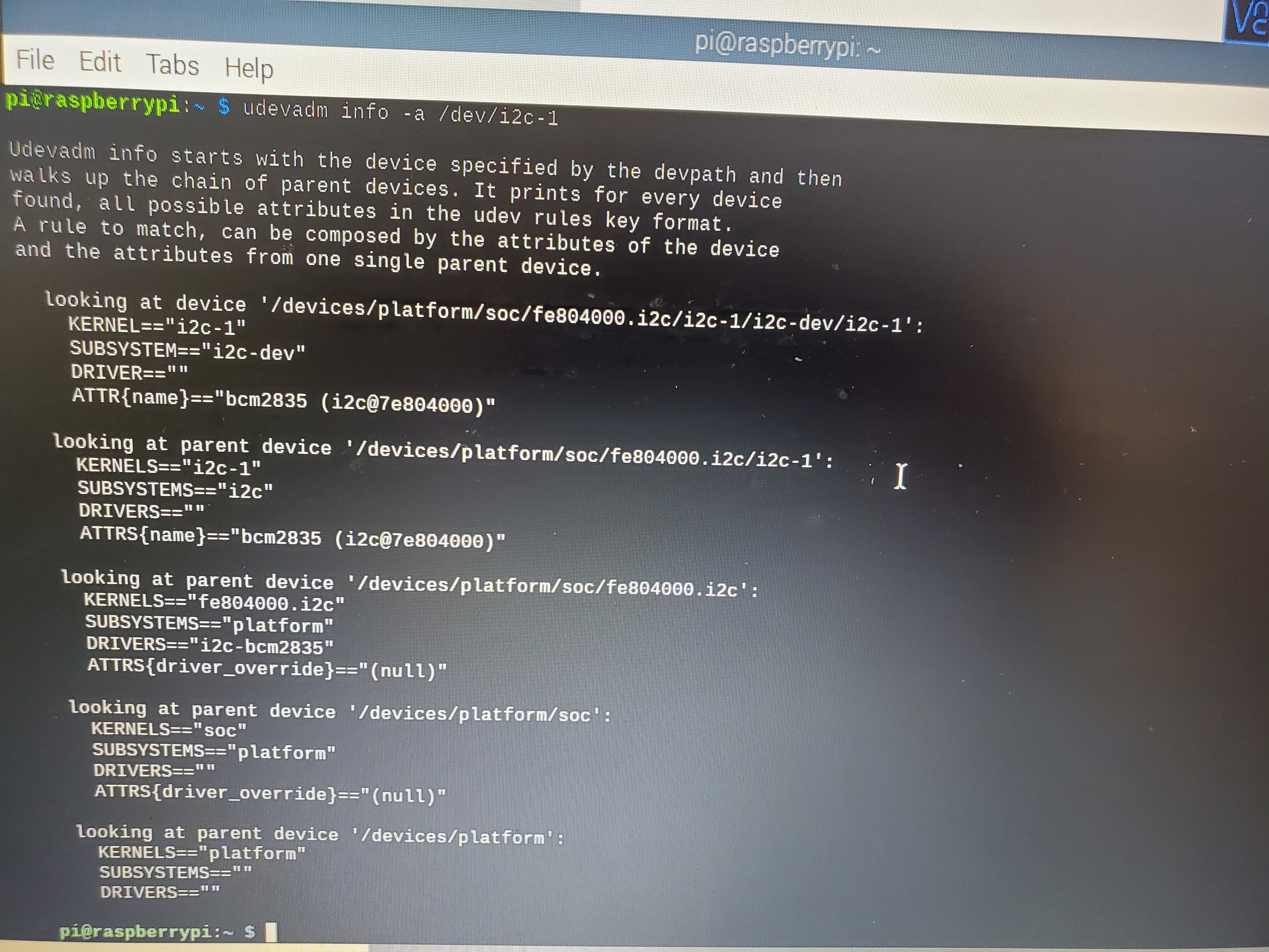
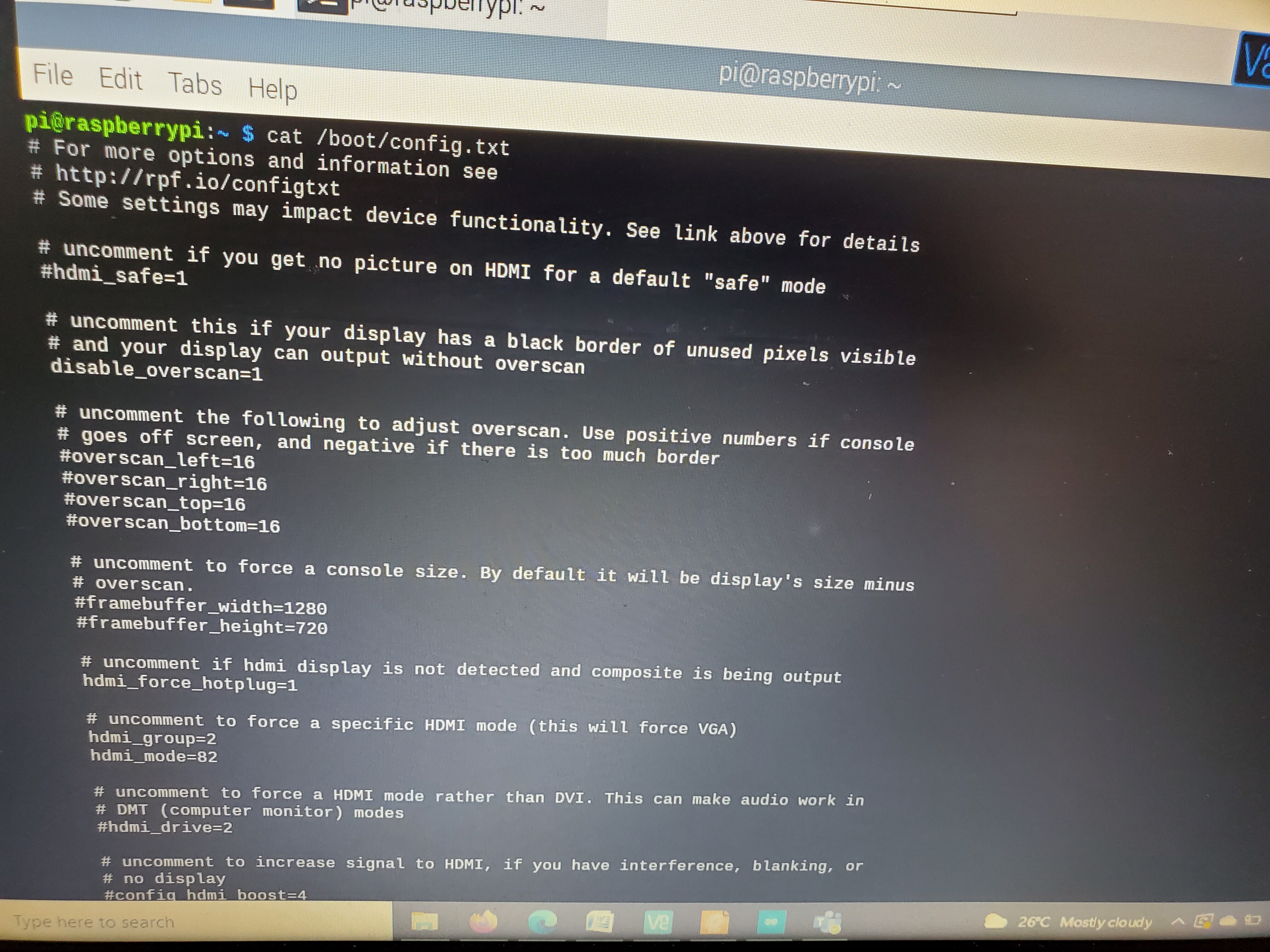
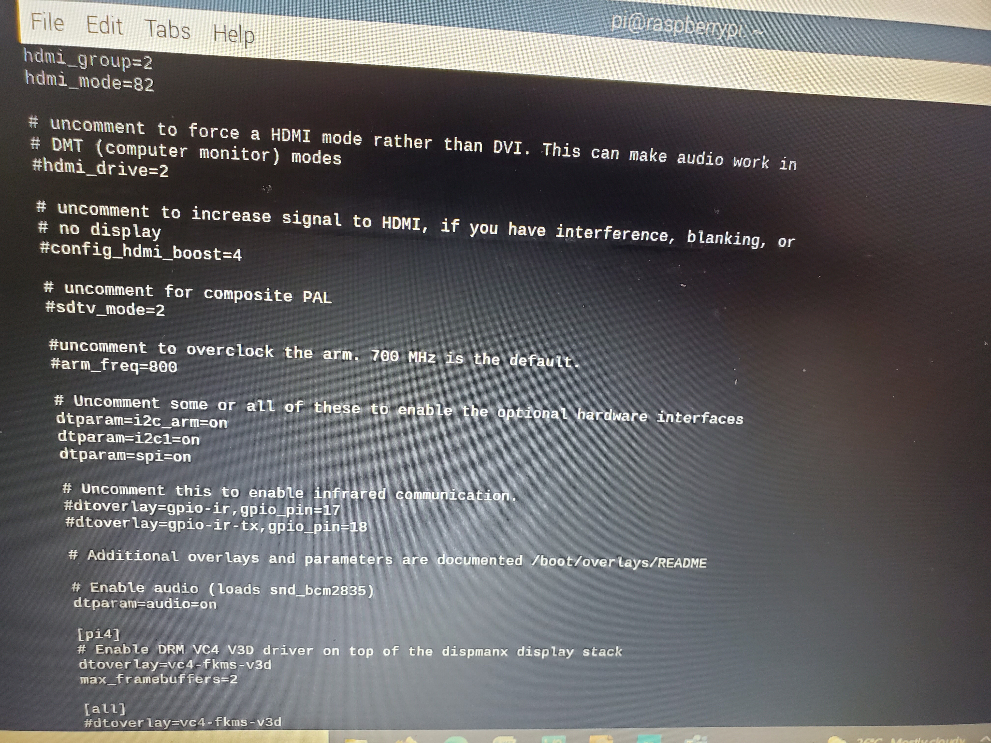
If you are still having trouble after simplifying your system, can you please give me more info so I can check what you’ve done? I’d like to see some clear pictures of the connections between the Raspberry Pi and the AltIMU-10 v5. Also, can you run the following two commands and post the full output from them here?
It looks you might be trying to use the header pins as push pins, but instead you will need to solder them to the AltIMU to ensure a good connection. The Adafruit Guide To Excellent Soldering has pictures of good solder joints.
If you continue to have trouble, please post updated pictures of your solder joints and connections.
Hello David,
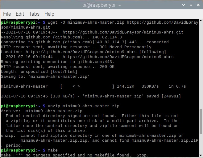
Thank you for your response.I soldered them and now it works.But I faced a new problem.After installing the libraries,according to this link:
David ,I solved the problem I faced github,I used “git clone”,I did “make” and “make install” successfully,now when I want to run:
minimu9-ahrs --mode raw
to test the module,there is an error:
Failed to open i2c device /dev/i2c-0
The code uses i2c-0 but in Raspberry pi,the module is connected to bus 1.which file should I make a change for the bus number?
Hello David,
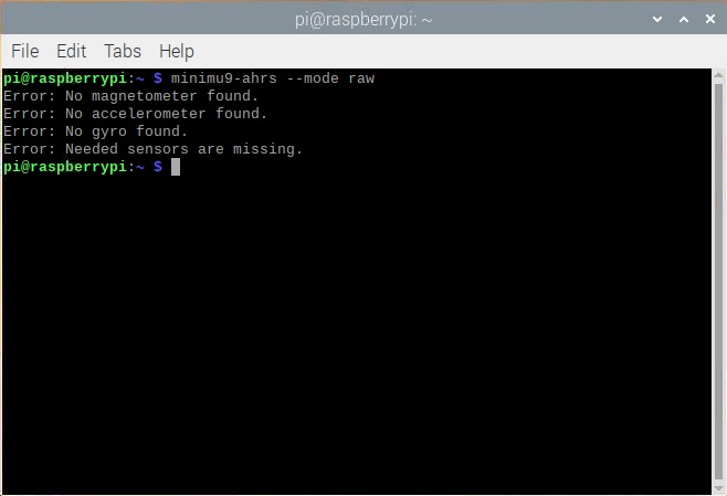
Thank you for your response.Now I faced another problem which you can see in the picture below:
I guess maybe the code is not completely compatible with Altimu10-V5.Is there anything for each sensor which I need to update in the code?The only reason for this problem which I can imagine of is that the code parts for each of the sensors cannot communicate to them but i2c can detect the three sensors,three addresses has been occupied.
What do you think about this new problem?
I just tested the AltIMU-10 v5 with minimu9-ahrs on a Raspberry Pi 3 Model B everything is working.
Today I added some debugging code to minimu9-ahrs so that we can get more details about what is happening on your system and why the software can’t detect your sensors. Please do the following things:
Use cd to navigate to your your minimu9-ahrs folder and then run git pull to get the latest version of the code.
Use a text editor to open i2c_bus.cpp, remove the // from the first line, and save the file. This enables the debugging code.
Run make and sudo make install to recompile the program and install it. (Let me know if there are any errors or warnings.)
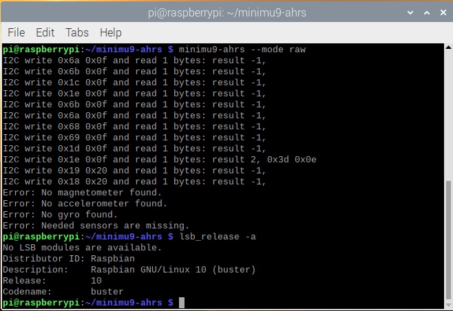
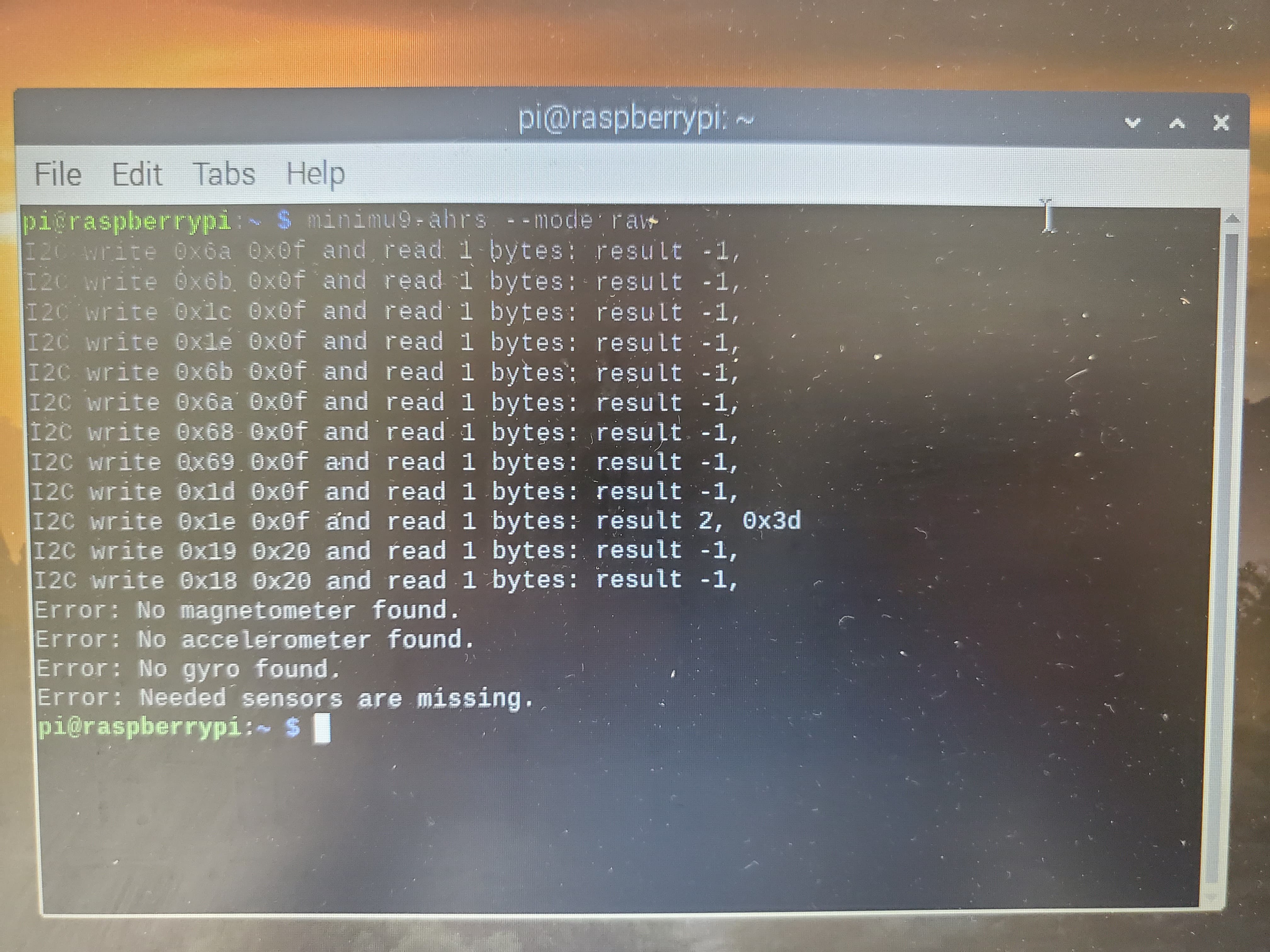
Run minimu9-ahrs --mode raw and post the full output here.
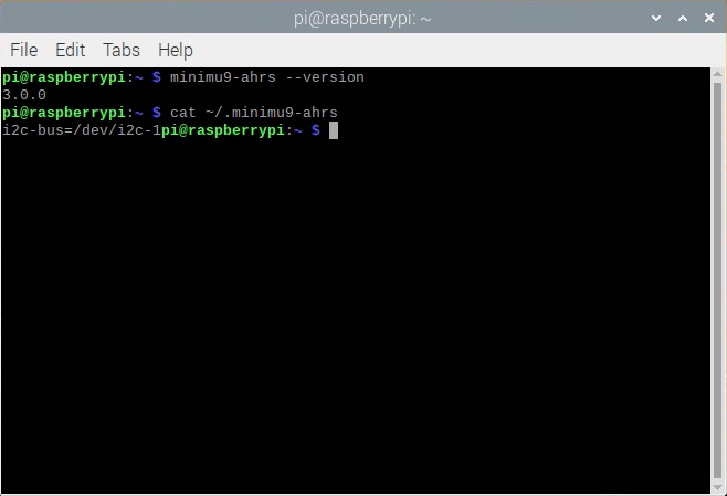
Also, what operating system are you running on your Raspberry Pi? Can you run lsb_release -a and post the full output here?
There was a bug in the I2C debugging code I sent you earlier, so please update your code again. To do this you should first run git checkout i2c_bus.cpp to undo your change to the top line of that file. Then you should be able to run git pull to get the new code.
The debugging output you sent indicates that the software is trying to read from the device at address 0x1e twice, but it only gets a response the second time. (That response is from the LIS3MDL on the AltIMU-10 v5.) Also, it should get a response from the LSM6DS33 both times it reads from address 0x6b, but it is not.
Addresses 0x1e and 0x6b were detected by i2cdetect, so I am not sure why minimu9-ahrs would have trouble talking to them like this.
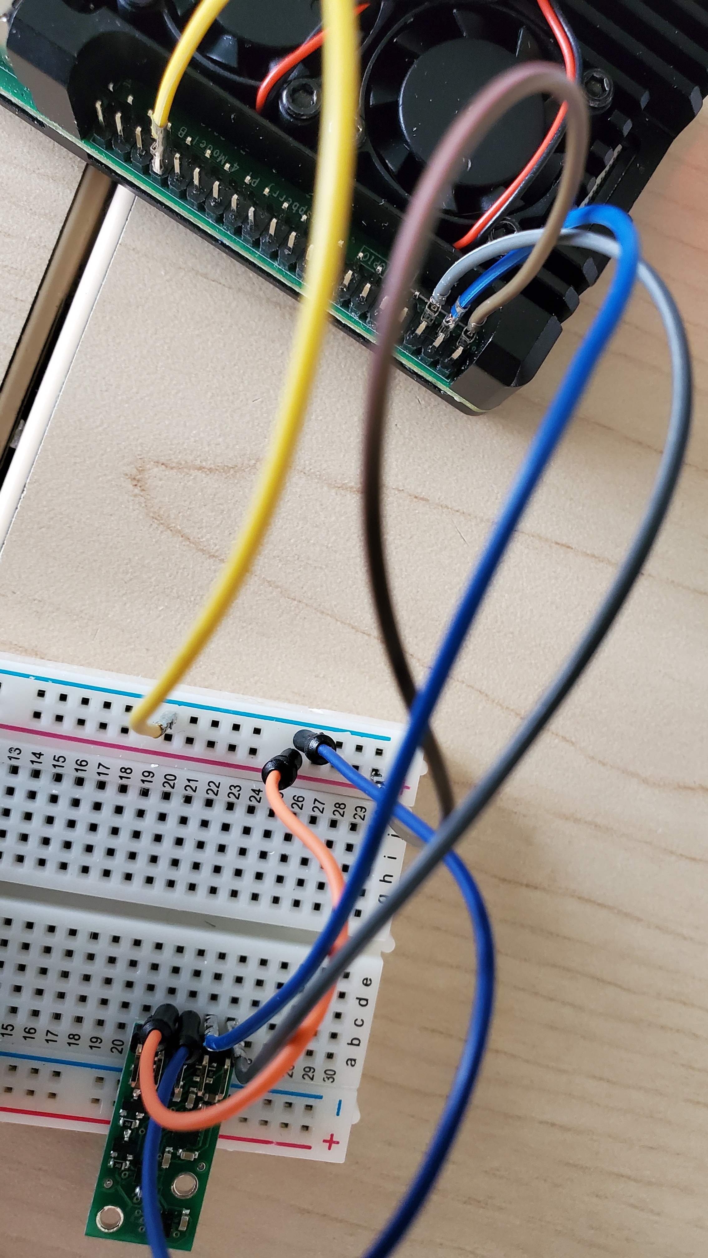
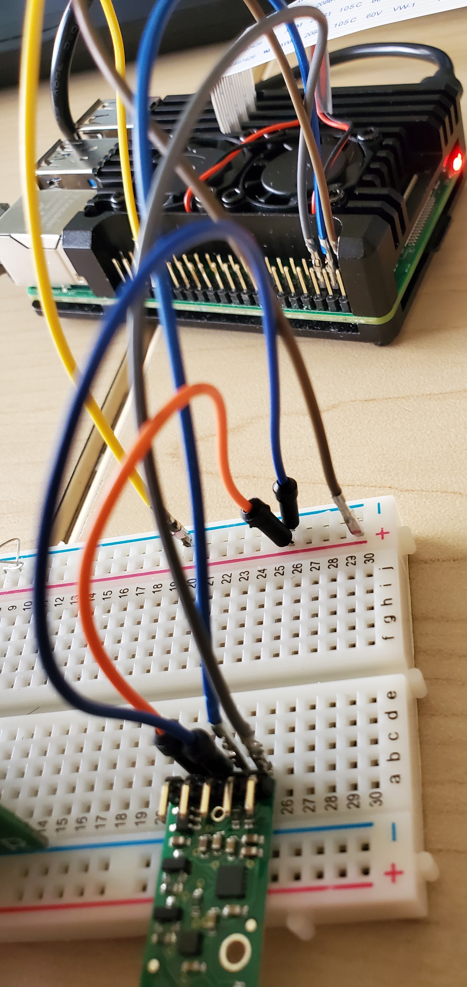
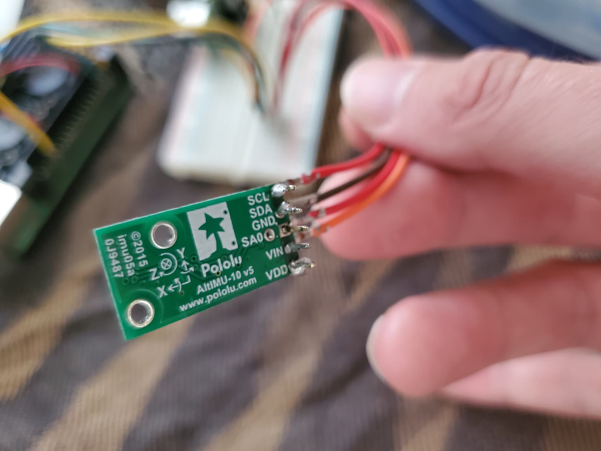
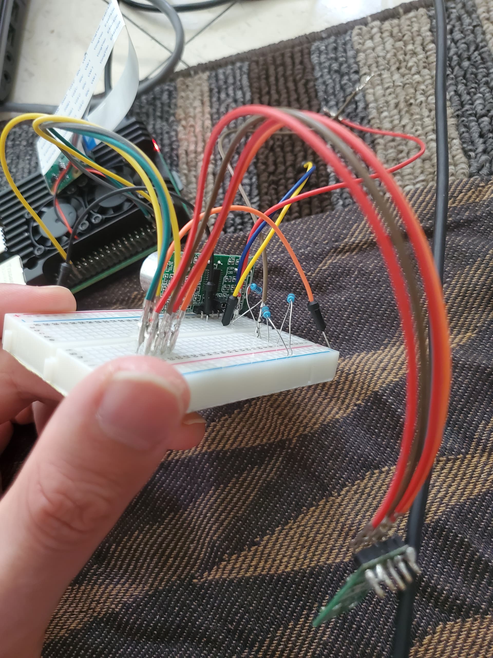
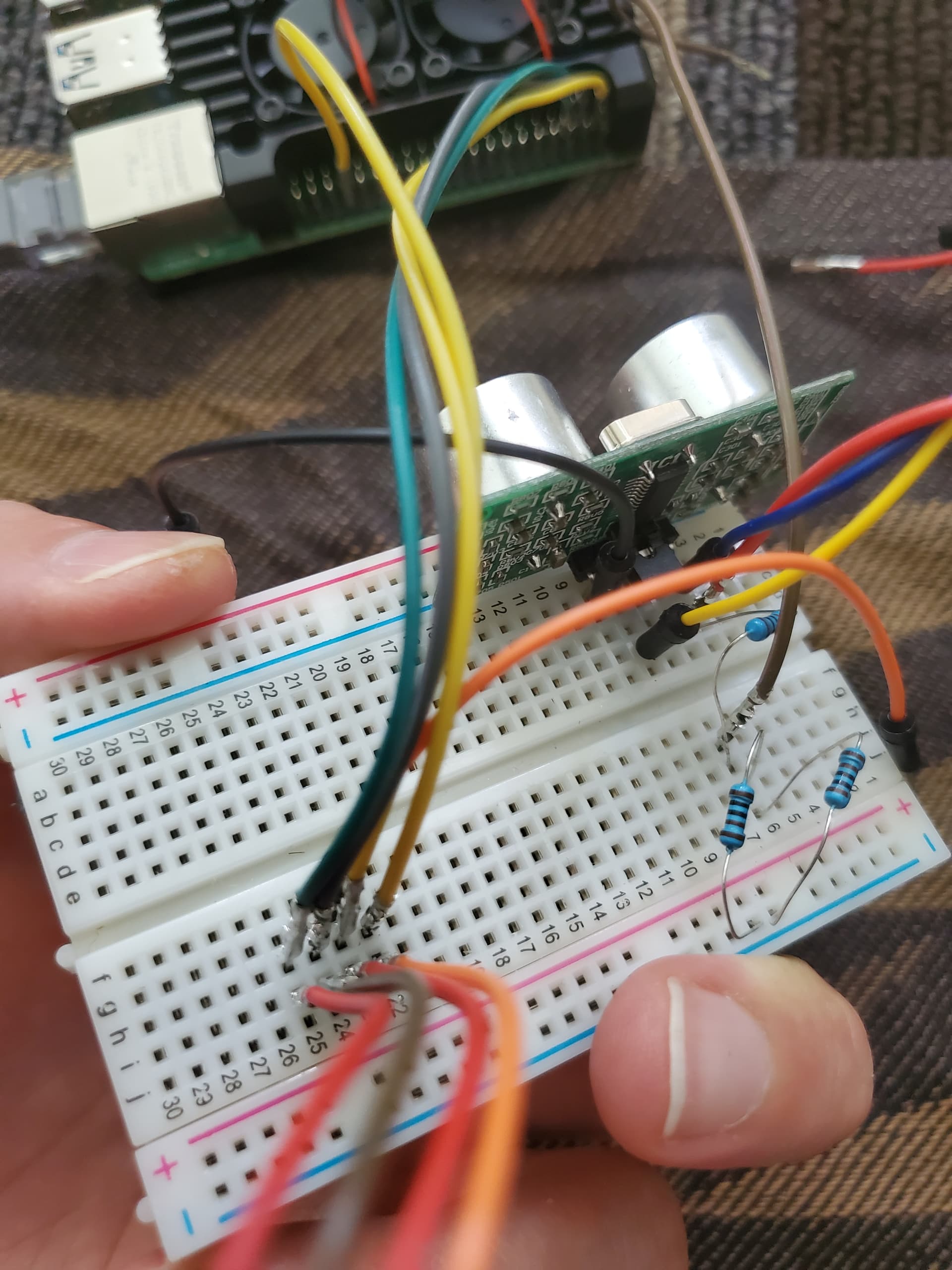
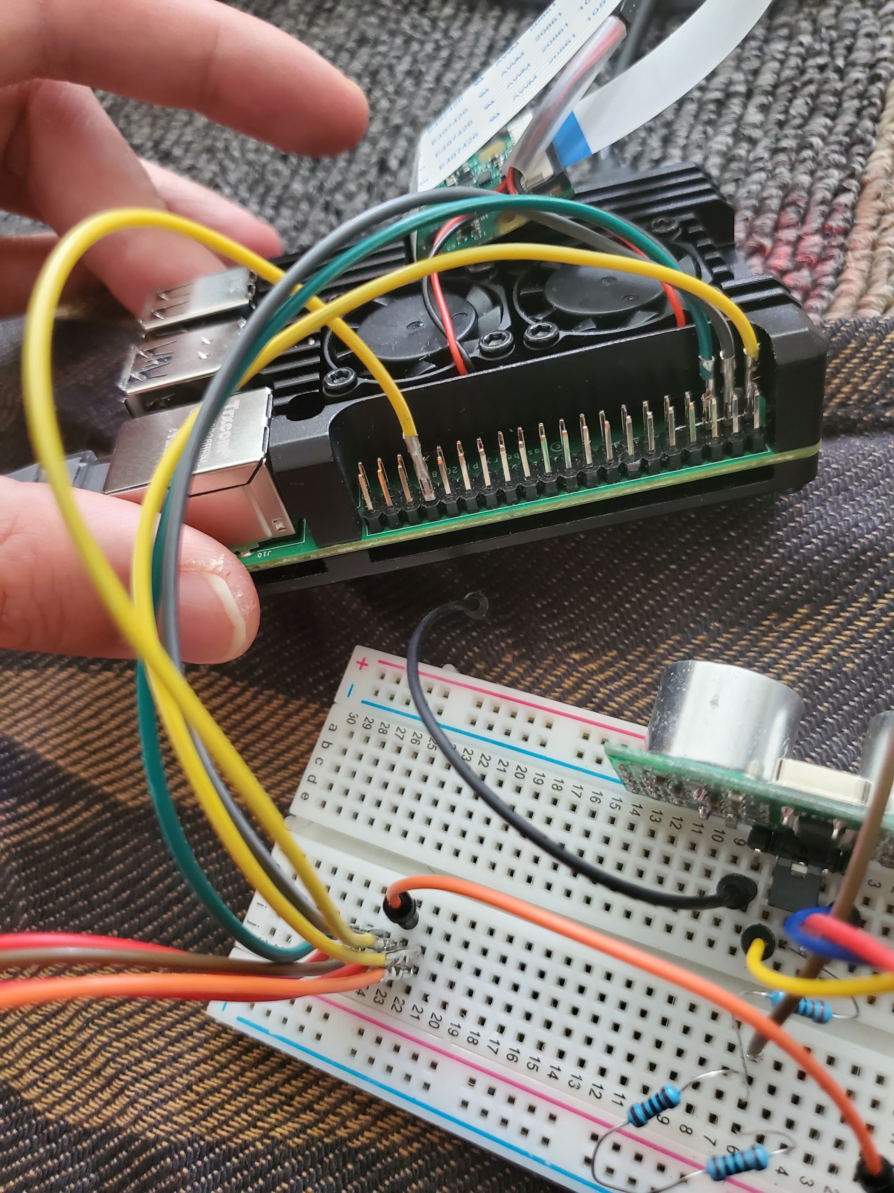
Could you post updated pictures showing your connections between the Raspberry Pi and the AltIMU-10 v5, and the solder joints on the AltIMU-10 v5?
Hello,
I updated the code in my Raspberry pi,these are the results,and I have my connections a bit complicated because I didn’t have female 2 female jumper wires.The soldering is a bit not accurate but I don’t think that is the problem.after soldering,the i2c addresses started to be detected and header pins are completely attached,they don’t move.
It looks like there is not much solder on the GND pin of the AltIMU-10 v5. Also, the solder on the SDA pin looks like it has not really flowed into the plated hole of the PCB. The “Common Soldering Problems” section of the Adafruilt soldering guide will help you tell what a good solder joint looks like. I recommend fixing the soldering on those pins and also checking the others carefully.