
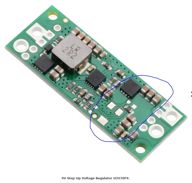
I bought a U3V70F9 voltage regulator to produce 9V @2A from 3.3V. To test this, I placed a 5ohm resistor between Vout (9V) and Ground. Assuming 80% efficiency, this should dray 6.14A @3.3V on the Vin side. The U3V70F9 regulator should be able to support up to 7A for extended durations according to the product info. Yet, when I try this the output is a sawtooth waveform between 4V and 9V (it ought to be a nice clean 9V source). Is there anything I’m missing?
Update: I tried this experiment again, but with 10ohm (half the current). This also didn’t work; but I noticed that if I hold my finger on the module; shown below: (
That the output becomes a clean 9V. The soldering looks OK to me, but it could be a bad contact on the QFN part. I tried touching it up with a soldering iron, but that didn’t produce any changes. It could also be that my finger added some capacitance.
I tried repeating the experiment with 5ohm; since I’d really like to see this thing handle 7A input, but adding my finger didn’t fully fix it (although it did help).
Hi.
Could you post pictures of your setup that show all connections including solder joints? We test each board before it ships, so it seems pretty unlikely that a component is not soldered well. If touching those exposed pads helps, it could be a grounding issue.
Please note that 2A out is right at the edge of what we expect that regulator to handle with 3.3V in and 9V out, so how well the board is kept cool could make a big difference.
-Claire
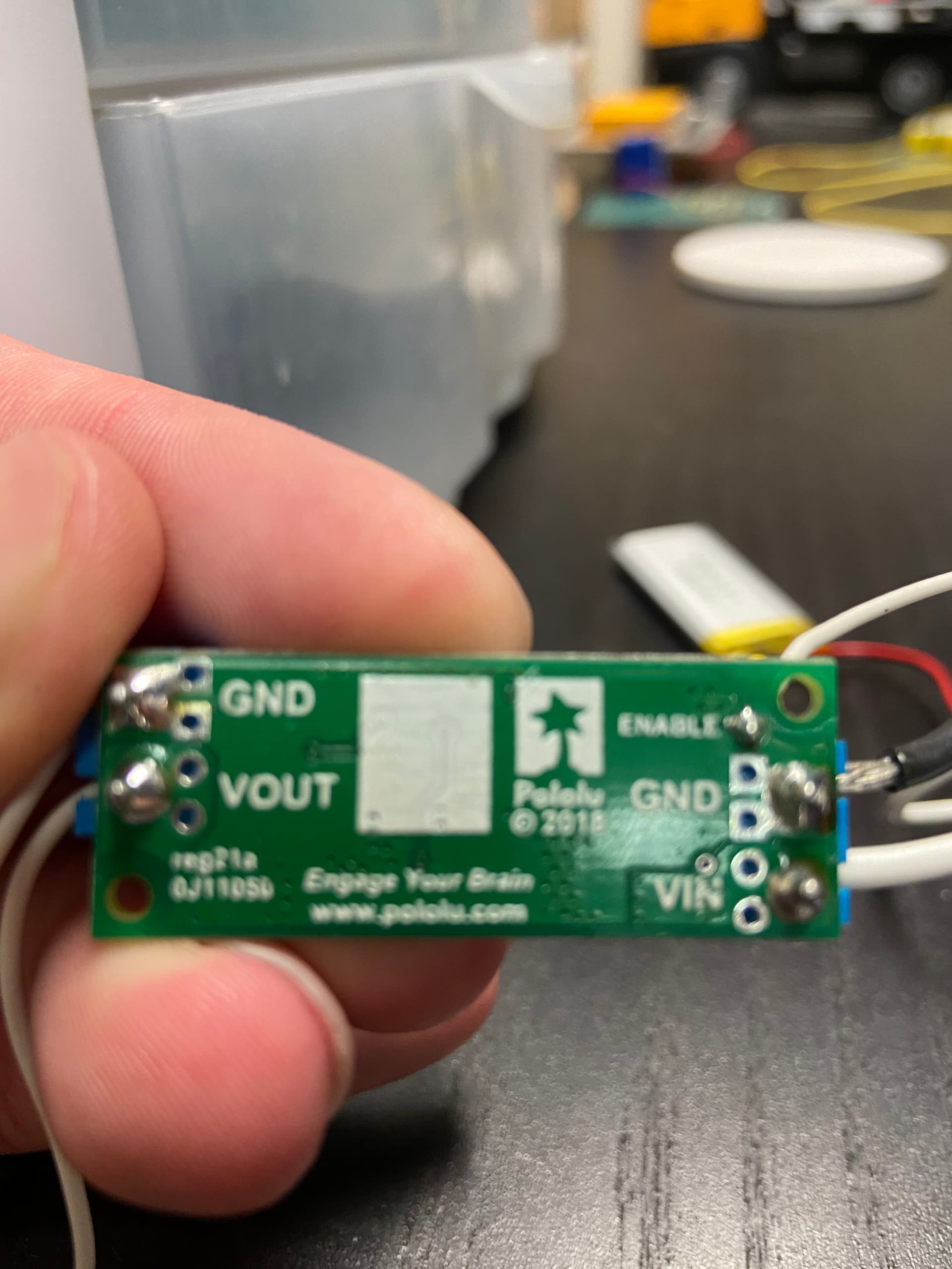
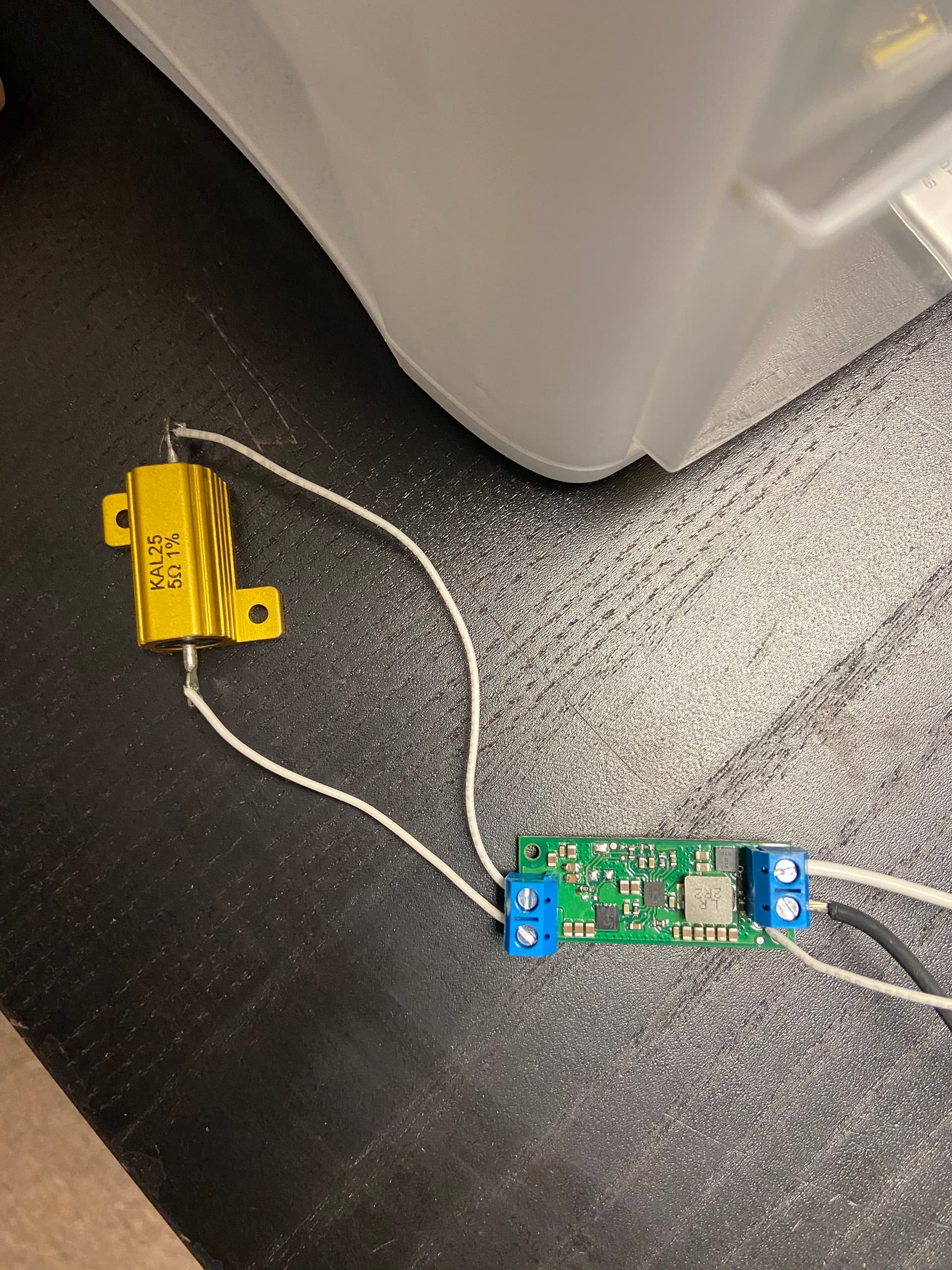
Here are two pictures of the setup, where the output runs to a 5ohm resistor and the input is just leads which I connect to a DC power supply. I used the screw terminals provided with the regulator (and included a picture of there soldering joints).
For this particular application I only need high current for about half a second (though it does need to be reasonably steady for that time). The board is at room temperature, and while running it I’ve never noticed the board getting hot.
I was also able to get this working for my application, by connecting it to 5V rather than 3.3V. The output is still pretty unstable (1.5V swings), by that’s good enough for my application. I would like to figure out though why it didn’t originally work.
Thanks for the pictures; the soldering and connections seem fine. What is connected to enable? Could you post some details about your power supply? Have you tried any other supplies? Does the output from the regulator look fine with no load?
In your previous post you circled a MOSFET that you thought might be affecting the regulator’s behavior. Could you try pushing down on just that MOSFET IC with a pen or pencil to see if the output still improves?
-Claire
I tried connecting the Enable pin to Vin (as expected this had the same effect as being left floating), I also tried connecting to the GND (which as expected disabled the regulator). In this picture Enable is tied to Vin. For power supplies I’ve tried all 3 DC power supplies I have available to me with both the 5ohm and 10 ohm loads, all with the same results.
With no load, or with low loads (i.e. 1kohm); the regulator preforms exactly as expected (clean 9V output). I didn’t test how low the load needs to be before this starts to happen (i.e. I could test 15 and 20 ohm loads, but haven’t yet).
I tried pushing on the area with a pencil eraser and wasn’t able to get the same effect as using my finger, which leads me to believe it was the added capacitance that was improving things (and unlikely it’s a structural issue). Is there any schematic available for this part? I could try changing the capacitance and seeing if that has any effect
I appreciate the additional information. I am not sure what the issue might be, so at this point it’s probably easiest if you try again with a new unit. Can you email us your order information for this regulator?
-Claire
Thank you for the help, I got the new unit. Unfortunately, I’m experiencing the same issue. My setup is the same as the picture (5ohm between Vout and GND); but I’m seeing the same sawtooth wave pattern as before. Are you able to confirm that the unit can operate with a 5ohm load?
As I mentioned before, 3.3V in and 1.8A out is at the edge of what the U3V70F9 can handle, so it might be overheating in your setup with 5ohms. Earlier you mentioned that your original regulator still did not have a steady output with a 10ohm load. Could you test with that with the new unit? Could you also measure the voltage directly at the VIN and GND through holes on the regulator board to make sure you are not getting a large voltage drop from the wires to your supply? I tested a unit here and saw a 0.7V drop over my 2.5’ cables between the supply and regulator with 1.8A out (so I actually had to set my supply to 4V to make sure the regulator was getting 3.3V at its input pins).
-Claire