I have been using the U3V70F5 converter to supply 15 WS2812B serial addressable LEDs an arduino nano MCU and a USB output. The input of the converter is from a 3.7 V 6000 mAh lipo battery with the TPS3700 voltage comparator as an over discharge battery supervisor.
The comparator disables the loads by disabling the output of the U3V70F5 converter by triggering enable pin at battery voltages < 3.2 V. There is however an issue when charging the battery back up above the comparators positive threshold which is at 3.3 V. The issue comes in the form of a reduced output at the DC to DC converter where a battery voltage of 3.25V would give 3.68V and a battery voltage of 3.28V would give 4.11V.
What is happening at the enable pin based on this evidence?? Is there a way to ensure that the comparator’s logic “LOW” would output 0 V at the converters output and a logic “HIGH” would output 5 V ?? These low output voltages would cause my WS2812B LEDs to be unstable so I would much rather restrict the voltage when charging up to 3.3 V and disable them when discharging down to 3.2V. How do I utilize the Enable pin to do this?
It sounds like your LED strips are drawing more than the regulator can handle when converting from 3.3V up to 5V, so the output of the regulator is not able to maintain 5V. I do not suspect the output of your comparator is the issue, though you could use a meter to monitor it to see for sure. For reference, a voltage below 0.4V on enable will disable the regulator and a voltage above 1.2V will enable the regulator.
From a quick search the datasheet I found for a TPS3700 comparator had a threshold of 0.4V. Do you have some additional circuitry like a voltage divider in your system for setting your threshold of 3.2V? Could you post a link to information about the specific comparator you are using and a diagram that shows all the connections in your test setup?
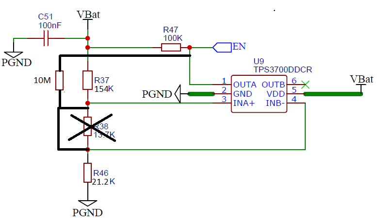
VBat and PGND would be connected to the converter’s Vin and GND inputs and the Enable pin is connected to the OUTA input of the comparator. The LEDs would have a max current draw of 1.2 A which is nearly 50% of the current capacity able to be outputted from the U3V70F5 so I doubt that the LEDs are pulling too much current.
I definitely think that there may be false positives being triggered when surpassing the 0.4V threshold of the comparator due to the voltage divider and low hysteresis built into the comparator. I just wanted to ensure whether the regulator would be able to go as low as 3.2 V and output 5 V without a worry when its enable is attached to the noninverting comparator’s output…
Claire is unavailable this week, but I am happy to continue helping you. If your load is drawing a maximum of 1.2 A, that should be well within the U3V70F5’s ability to output at 5V with a 3.3V input, so it does sound like problem is elsewhere.
I suspect something like what you described is happening, where the comparator is repeatedly turning the regulator on and off as the battery voltage drops when the load is powered and recovers when it is unpowered. I recommend looking at VBat with an oscilloscope to see if that is the case (and you could also probe the comparator’s output/regulator’s enable input to see if some corresponding switching is going on).
I shall try altering my hysteresis a bit by adding an additional resistor parallel to my OUTA and enable points and changing the voltage divider resistor ratio to increase the hysteresis up to 100mV and check to see if this makes any difference in performance. I have attached an image of the changed circuit of my comparator below with respect to my regulators enable pin: