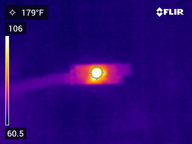
I hooked up my U3V70F12 to my Keysight E36312A bench supply. I set the bench supply for 3.7 V with a current limit of 2 A. When I power up the U3V70F12 from the bench supply with NO load attached to its outputs, I see a current of just over 500 mA and an output voltage of only 7 V. It also gets quite warm–in excess of 120 F.
Looking at the quiescent current graphs on the product page, I’d expect a current closer to 2.5 mA; not 500 mA.
I double checked the polarity of my connections. I tried adding a 33 uF capacitor at the input terminals too. Do I need a minimum load?
Also, want to add that my final goal is to drive a 12 V coil at 600 mA for 5 ms 12 times a day.
I could settle for charging a bank of caps to 12 V at a low current (e.g. 20 mA) through a diode, switching off the regulator using an external high side transistor switch, then discharging the caps through the coil and a transistor if I had to.
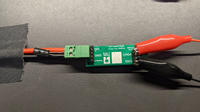
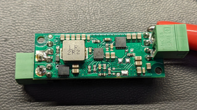
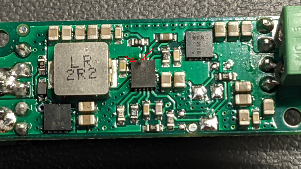
The U3V70F12 should not need any load or added capacitance to work, so it does seem like something is going wrong with the regulator or your setup. Is the 500mA you are seeing the draw reported by your supply (i.e. the input side of the regulator)? Does anything change if you change the supply’s voltage or reduce the supply’s current limit? The soldering on the pins for the terminal blocks on the VIN side of the regulator looks like it might not be fully wetted. Could you try retouching that? You might need to increase the heat on your iron or leave the iron on the joint longer since all the copper around those terminal block holes can suck the heat away quickly.
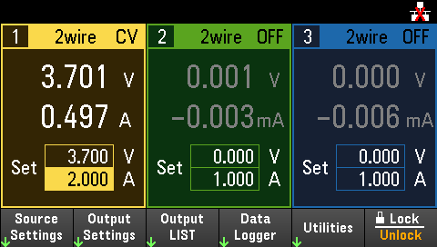
The regulator is connected to channel 1 which is the yellow pane in the image. The CV at the top right indicates the channel is running in constant voltage mode. The 3.701 V is the voltage being supplied to the regulator board. The 0.497 A is the current being pulled by the regulator board. The 3.700 V is the voltage set point and the 2.000 A is the current set point. If the current gets to 2.000 A, the supply will go into constant current mode and begin tapering down the voltage to prevent more than 2.000 A from being supplied to the regulator. Since “CV” is at the top, this is not the case.
The measurements on the power supply are usually within +/-2 mV and +/-2 mA of my bench DMM so I trust the measurements on the power supply. I did not use the bench DMM to verify the measurements in this case because there’s really no need to.
I bumped the voltage set point up to 6 V. The current maxed out, the supply went into CC mode, and it tapered the voltage down to about a volt. While this was happening, I started to small a weird smell and I shut down the supply before I had to chance to grab another screen cap at 6 V. The regulator IC now has a small hole in it.
Since the board has no thermals, I had a hard time soldering the terminals and the board got quite hot. I’m wondering if I overheated the board just soldering the connectors. The other possibility is that the leads from the power supply are 36" so maybe that note about long lead lengths and voltage spikes apply.
I may try some cheap off-brand imported boost converters and see if I make progress with them. If I do, I may come back to this board. Anyway, I can progress on my project using my bench supply in place of a boost converter for now.
The IC on the regulator looks damaged now, and it seems likely that it was damaged before. Connecting long wires can result in voltage spikes, but since your supply voltage is so low, that seems unlikely to have been the cause of the damage. If the ground connection on the terminal block was not connecting well, that could also cause a situation where current is flowing through a logic connection, which could damage the chip. If you want to try again with a new U3V70F12 please email us with a link to this thread and your order information.