I’ve been testing the U3V70A (2890) regulator for potential use in a product. Unfortunately the UVLO feature isn’t working as expected. I was wondering if I could get the P/N for the actual regulator chip that’s on this board so that I could look up more detailed specs on it?
For context, I’m operating the regulator from two 18650 batteries that are essentially paralleled. The regulator output is set to 5 V and the load current is ~1.0-1.25 A (resistive load only). There are some “small” resistances in the path between the 18650 batteries and the regulator - a FET, some short wires (20 AWG), etc. These resistances are on the order of 50-100 mOhm. When the battery is at full voltage (4.2-ish V), the regulator draws around 2 A. As the battery voltage falls, the regulator input voltage approaches the UVLO falling threshold of 2.4 V. At this point, the current drawn by the regulator input is around 3.3 A.
During normal operation, the current flowing into the regulator causes a voltage drop along the parasitic resistances. When the battery voltage gets low enough, the UVLO feature shuts off the regulator. This drastically reduces the input current, thus eliminating the parasitic voltage drop. This causes the input voltage seen by the regulator to bump back up slightly, but not enough for proper regulator operation. I’ve seen it bump up anywhere from 2.4-2.9 V under different circumstances. When this happens, it seems to enter an indeterminate state and begins regulating at lower voltages than 5 V (i.e. voltages other than what it’s set for).
I’ve been working on reducing the parasitic resistances, so I’d rather not get sidetracked by that. Instead, I’d like to understand why the regulator’s UVLO isn’t causing it to either stay off completely or only power back on when there’s sufficient voltage to operate properly. I believe this is the primary purpose of a UVLO feature.
What I see is that if the UVLO shuts off the regulator, but then the regulator input voltage jumps back up to somewhere between the UVLO falling threshhold (2.4 V) and the minimum regulator Vin (2.9 V), the regulator has a problem.
We do not disclose the specific regulator IC used on those regulators, but I am happy to help you troubleshoot the situation. Is it possible the input voltage is rapidly oscillating between <2.4V and >2.8V as the regulator repeatedly turns on and off? How are you measuring the supply voltage? If you are not already doing so, could you try looking at it with a scope and also post some screenshots? I also recommend doing the same with the output voltage of the regulator.
Thanks for the reply - I appreciate the help. And I completely understand about not being able to share the actual regulator IC P/N. Some companies do and some companies don’t, which is why I thought I’d ask.
I’ve got a couple things I want to try today, but I may also get the scope shots you recommended. Thus far it’s been all DMM work - it hadn’t gotten complicated enough for scopes yet. But, alas, we might be there now.
BTW, using only DMMs I’ve seen the oscillations you described - though the voltage levels may have been slightly different. But they were in that ballpark. The oscillations were slow enough that the DMMs could pick them up (on the order of seconds). But then they stopped & the regulator seemed to settle in this indeterminate state where it was outputting something other than 5V.
What I think you might be suggesting is that even this state may actually be undergoing oscillations, it’s just that they are much faster. The DMMs wouldn’t be picking them up and may instead give the appearance of an indeterminate state with an output that’s out of regulation (i.e. not 5 V). Good point. I hadn’t thought of that.
Anyway, I will do some more testing & keep you posted. Thanks again for the help.
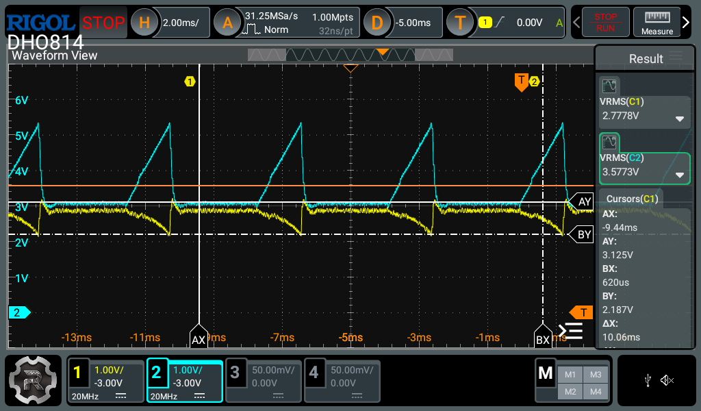
I decided to get your scope captures before trying my other experiments. For convenience, I used a benchtop power supply instead of the 18650 batteries. Indeed, the regulator is oscillating as you described.
Trace 1 is the regulator input voltage, trace 2 is the output voltage. Both are measured at the regulator board. You can see that the input voltage oscillates roughly between the UVLO falling threshold (2.4 V) and the UVLO rising threshold (2.8 V). It’s not exact, but it’s in the right ballpark.
So the regulator really wasn’t entering an indeterminate state, it was just going from slow oscillations that my DMMs could accurately respond to (on the order of seconds), to faster oscillations that they couldn’t accurately respond to (i.e. milliseconds). Once that happened, they were just giving me RMS values of the oscillating waveforms, which resulted in a stable - but misleading - number. But the scope tells the full story.
Anyway, it seems like the fix here is really just to minimize the DC resistance in the path from the batteries to the regulator. This will avoid a voltage drop along the path, which is what ultimately causes the oscillations.
If you have any other suggestions, please let me know - maybe I’m missing a better solution.
Minimizing wire resistance sounds like a good plan.
If you haven’t already, you might also try different batteries (e.g. newer ones, a different brand, or different type) to see if there’s any difference.
If your application allows for it, another solution might be some kind of failsafe or latching circuit that disables the load once the regulator shuts off and keeps it off until it’s manually enabled again.
Just wanted to close the loop on this. Ultimately, we were able to reduce the resistance between the batteries & the regulator input. This eliminated the oscillations.
Thanks again for your help. I really appreciate it.