I have just bought 2 U3V12F5 step up converters and the efficency curve that is shown on the product page does not seem to be correct (or both of my converters are faulty?). I have boosted a LIPO (with 3,90 V at no load) to 5 V. I measured the following voltages and currents when using a 22 Ohm and a 10 Ohm resistance over VOUT-GND (output stable at 5V):
I calculate efficency as Eff=V_outI_out/(V_inI_in).
In the first case, from the 5V-curve on the product page one would expect an efficency close to 90%, but even in the second case it should be well over 80%, however we get only about 80% and 60%! Do I have bad converters or is the curve on the product page incorrect?
I need to boost with 600mA output with an efficency over 80%, so my power supply can handle it. From the product page this seemed to be the right converter, but something goes wrong, could you help on this subject?
How are you measuring voltages and currents? Keep in mind that measurement instruments perturb both voltages and currents.
For example, there might be a significant voltage drop across the device measuring the input current, so that the boost converter does not see the stated input voltage.
For another example, 5.00 V/22.0 ohms = 0.227 A, so the I_out measurement is either incorrect in that case, or the “22 ohm” resistor is not 22 ohms. Are you taking component tolerances into account?
Of course the resistors are not exact, this is why I report current and voltage. Voltage is read by a digital multimeter, as it has a very high impedance this should not influence the meassurement at all. I measure current with another multimeter, which might have a little impedance but at least it is so small I can’t measure it with my Ohmmeter, so it is smaller than 1 Ohm (should be much smaller!)
Anyhow, we are not talking about small 1-2% errors, we are seeing a difference in efficiency of 80 vs 60 here which is 20/80=25% less efficient than expected.
Your reported efficiency is below what we expect. Can you confirm that your input voltage measurement is at the regulator, not at the power source? With over an amp input current, even half an ohm total resistance in your power leads and current meter will already cost you almost 20% of your input power.
If you are measuring the input voltage right at the regulator, the next thing I would recommend is adding some capacitors at the input in case noise on your input is throwing off the meter reading. If you still have problems, can you post a picture of your setup?
Yes the input voltage has been measured directly at the input (VIN-GND). I had detected the problem in a power supply I am building and in order to eliminate other sources of error I sticked the device directly in a bread board where I did these measurements. The setup is just a 5W resistor (22 and 10 Ohm) from VOUT to GND and a 1-cell LIPO from VIN to GND.
What kind of noise should I expect from the LIPO? Or does the breakout board generate oscillations on the input?
In the meantime I have repeated the measurements with a S7V7F5, I obtain slightly better results with 87% (this is ok at 0.2A) and 64% (at 0.5A output still quite bad) for the same parameters.
I tried with 100 nF and 10uF, no changes in current and voltage readings.
But I have observed some errors: input current goes down about 10mA to 1,04A during the first 10 secs or so (why?, device reaching working temp?). Also I have measured output as 5.15V today, and input voltage as 3,46V directly at the solder pads which gives us 72% of efficiency for 0.5A output after the transient phase, still not the same as on the curve, but better.
Would it be possible to try this simple measurement at Pololu and post the results here? You just need a 5W 10 Ohm resistor, the booster and a Lipo.
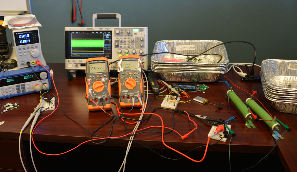
I just tested one of those regulators with both a LiPo battery and a programable power supply and measured efficiencies of at least 80% for 10ohm and 22ohm resistances. Below are the numbers I got and a picture of my setup.
Thank you very much Claire, you for shure have a better setup than me The fundamental difference is you have good wires and clamps everywhere, and I used the bread board jumpers. So I went and soldered everything as close as possible together eliminating the bread board connections and thin wires and voilá I got 81% ! Thanx for trying this out, it made me rework my naive initial setup and now I am getting what I initially expected!

 The fundamental difference is you have good wires and clamps everywhere, and I used the bread board jumpers. So I went and soldered everything as close as possible together eliminating the bread board connections and thin wires and voilá I got 81% ! Thanx for trying this out, it made me rework my naive initial setup and now I am getting what I initially expected!