Hi all — hobbyist here working on a mobile robot project. I searched the forum for similar issues but didn’t find an answer, so hopefully this is okay to ask.
My setup: an 8S LiFePO4 battery (about 26 V, up to ~29 V fully charged) feeds a busbar, and from there two D42V110F18 regulators each power a Jetson Nano at 18 V. Battery power to the regulators goes through a homemade MOSFET switch board that a Raspberry Pi Pico controls. Everything had been working fine.
Today I needed to update the firmware on the Pico, so I shut down both Nanos, powered the Pico off, and restarted it. A second or two after the Pico came back up, I heard a pop — at first I thought something fell off the table, but it was both regulators dying at the same moment.
What I’ve checked so far:
- Each regulator has ~26 V going in but 0 V coming out
- It doesn’t seem to be the enable pin — the output is still 0 V with ENA disconnected
- I don’t measure a short on the outputs
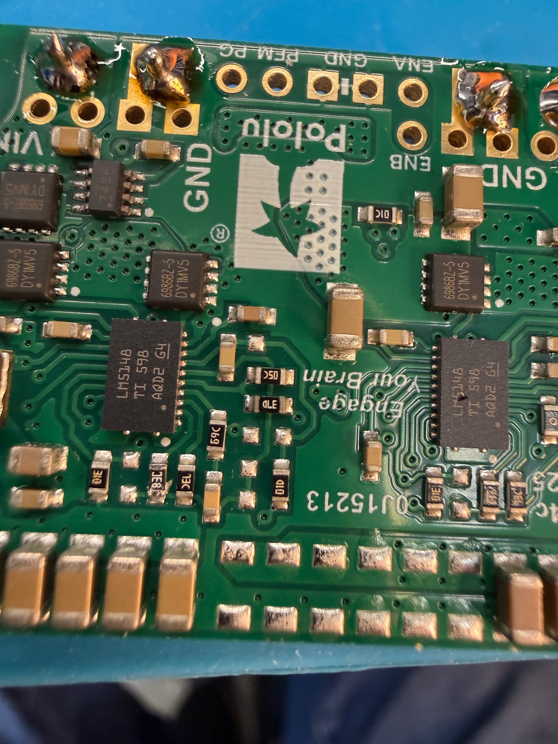
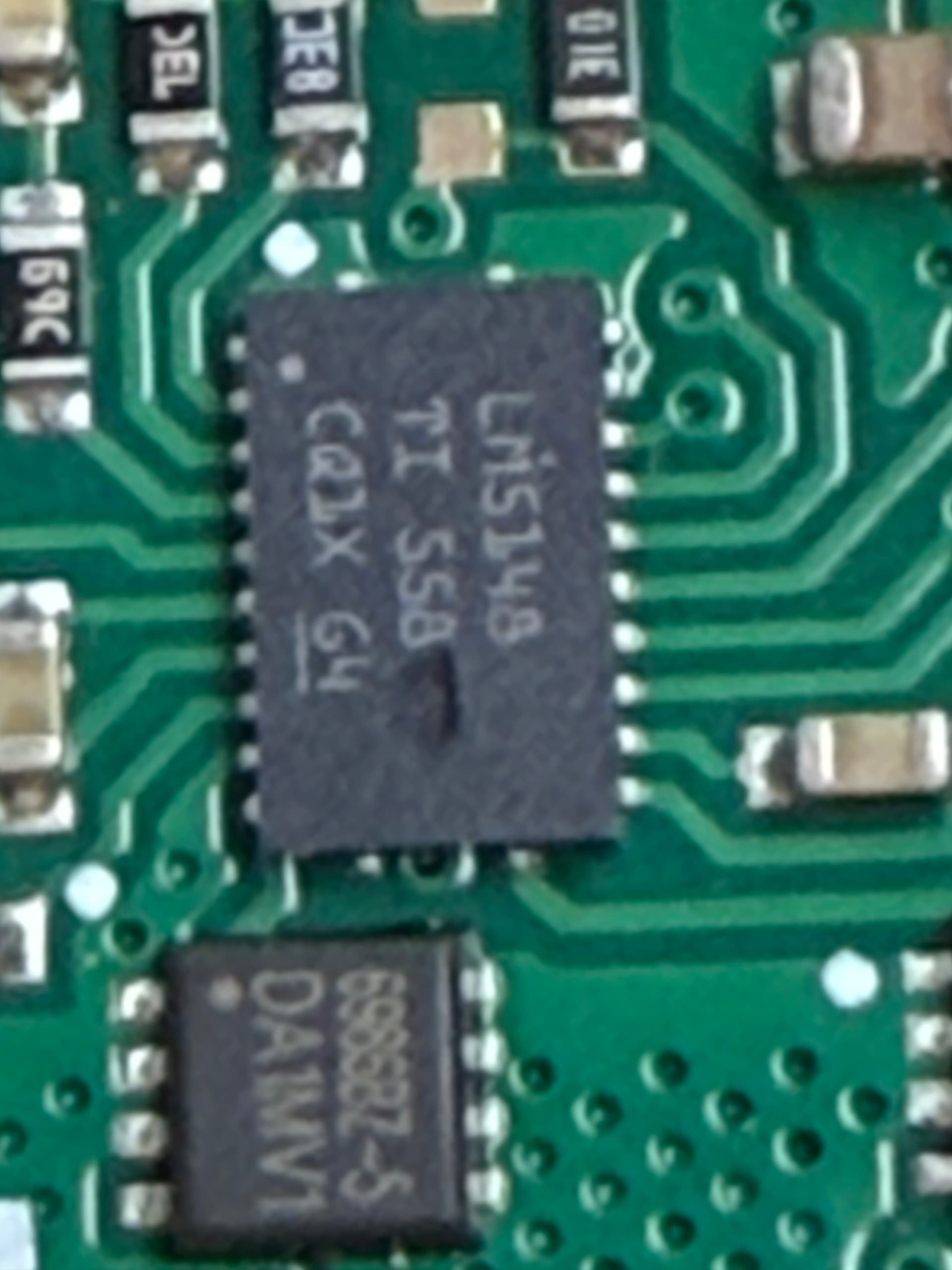
- Both boards have a similar-looking dark mark or pit on the LM5148 chip (photos below)
- The Nanos themselves seem to have survived — one boots fine from a bench supply
My guess is that when the Pico rebooted, my switch board cut power and then reapplied it abruptly. I’ve seen the warnings about voltage spikes when connecting power to these regulators through long wires, and I suspect that’s what got me — the MOSFET switch probably makes a much harder edge than plugging in a connector. I’d like to confirm that before I buy two more and repeat the mistake.
So my questions:
- Does the damage in my photos look consistent with that kind of voltage spike?
- Would a TVS diode and some extra capacitance at the regulator inputs be the right fix, and if so, what values would you suggest for a ~26–29 V battery?
Photos of the marks on both LM5148 chips attached. Thanks for any help!
Hello, Heather.
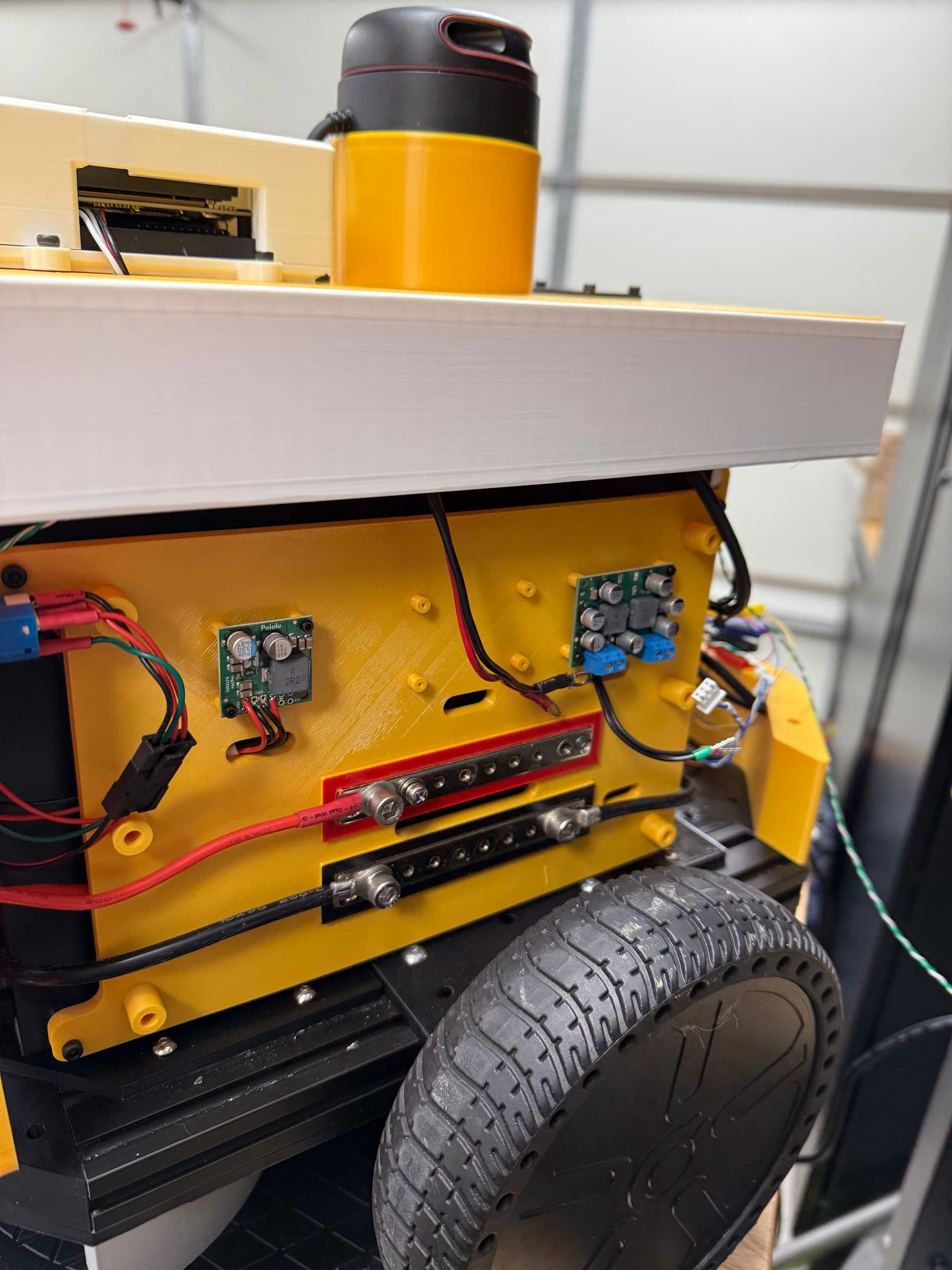
We have not seen this kind of failure before. Can you post some broader pictures showing all of the connections and your overall system? Please also email us with your order information and a reference to this thread. If you send them back to us, we can look into them more on our side to try to determine what might have happened.
- Patrick
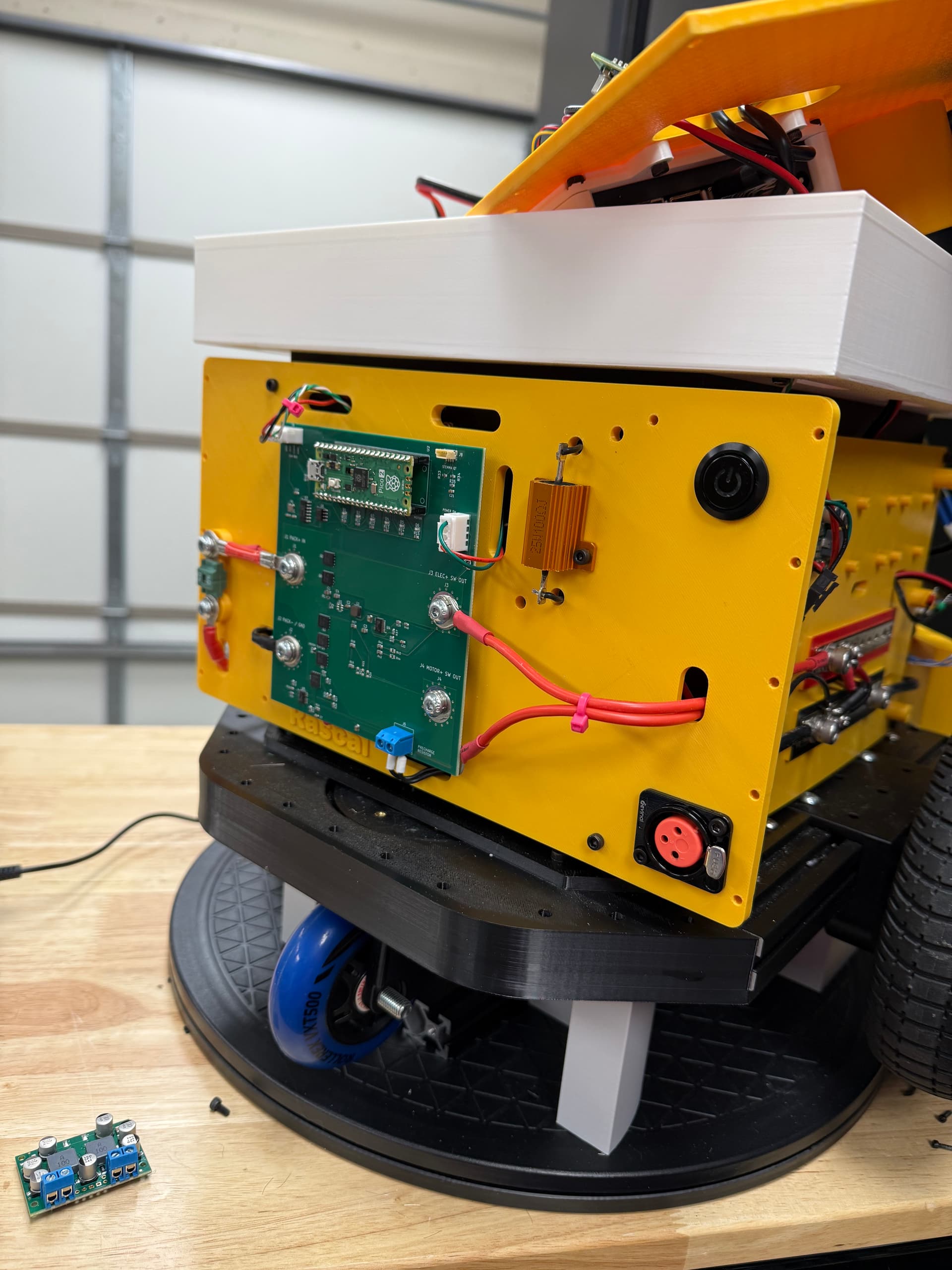
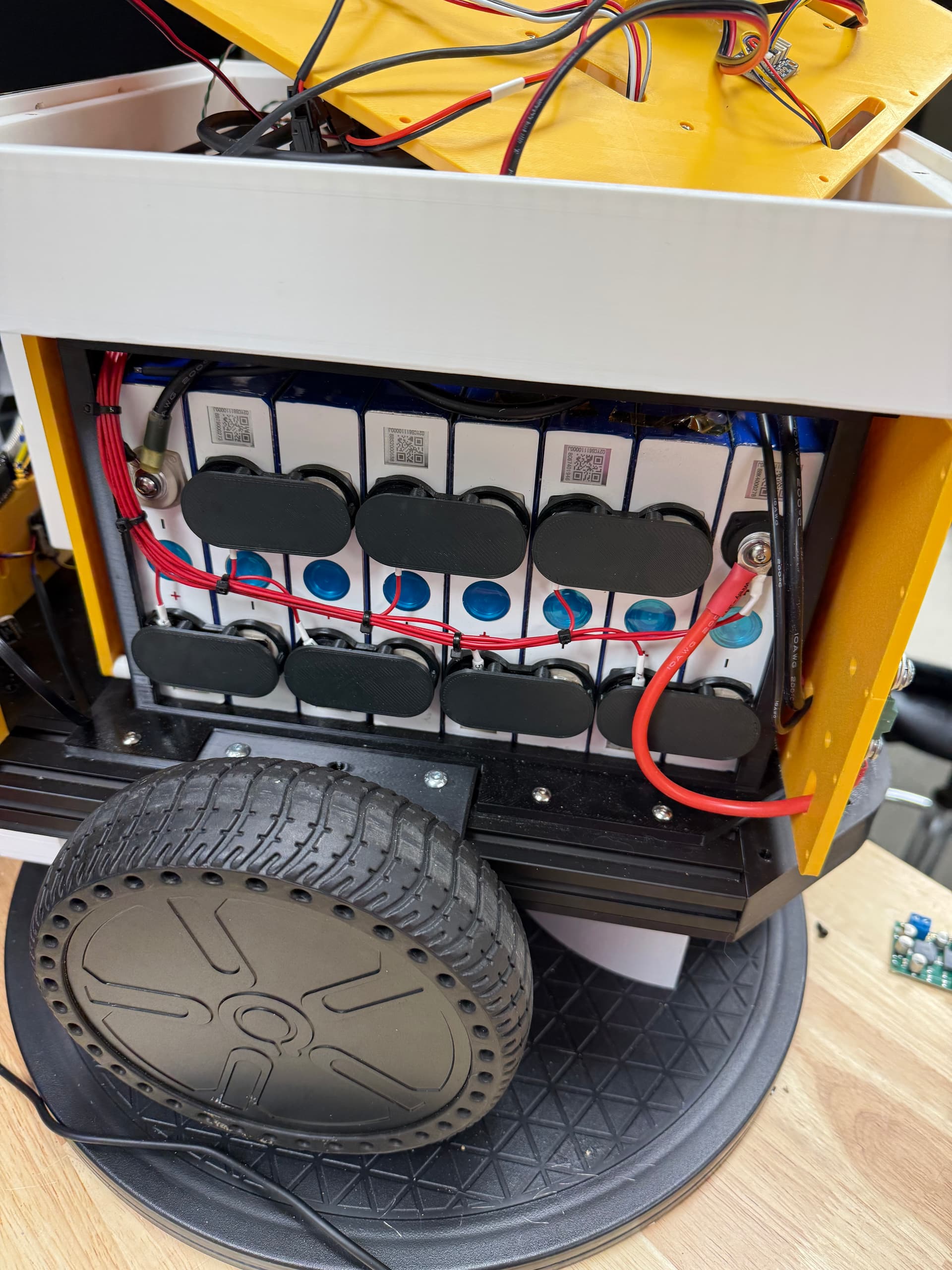
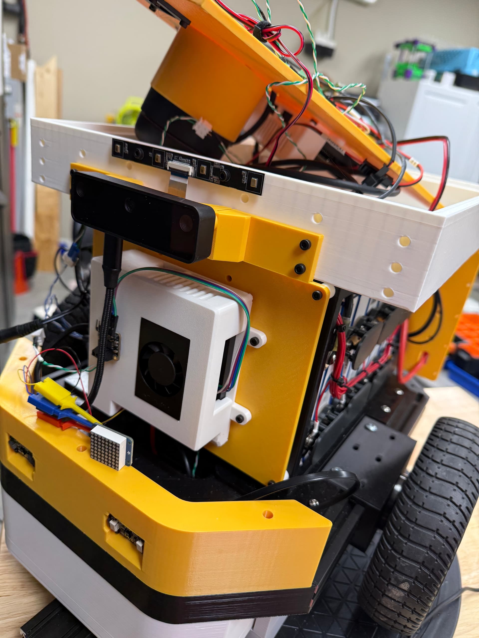
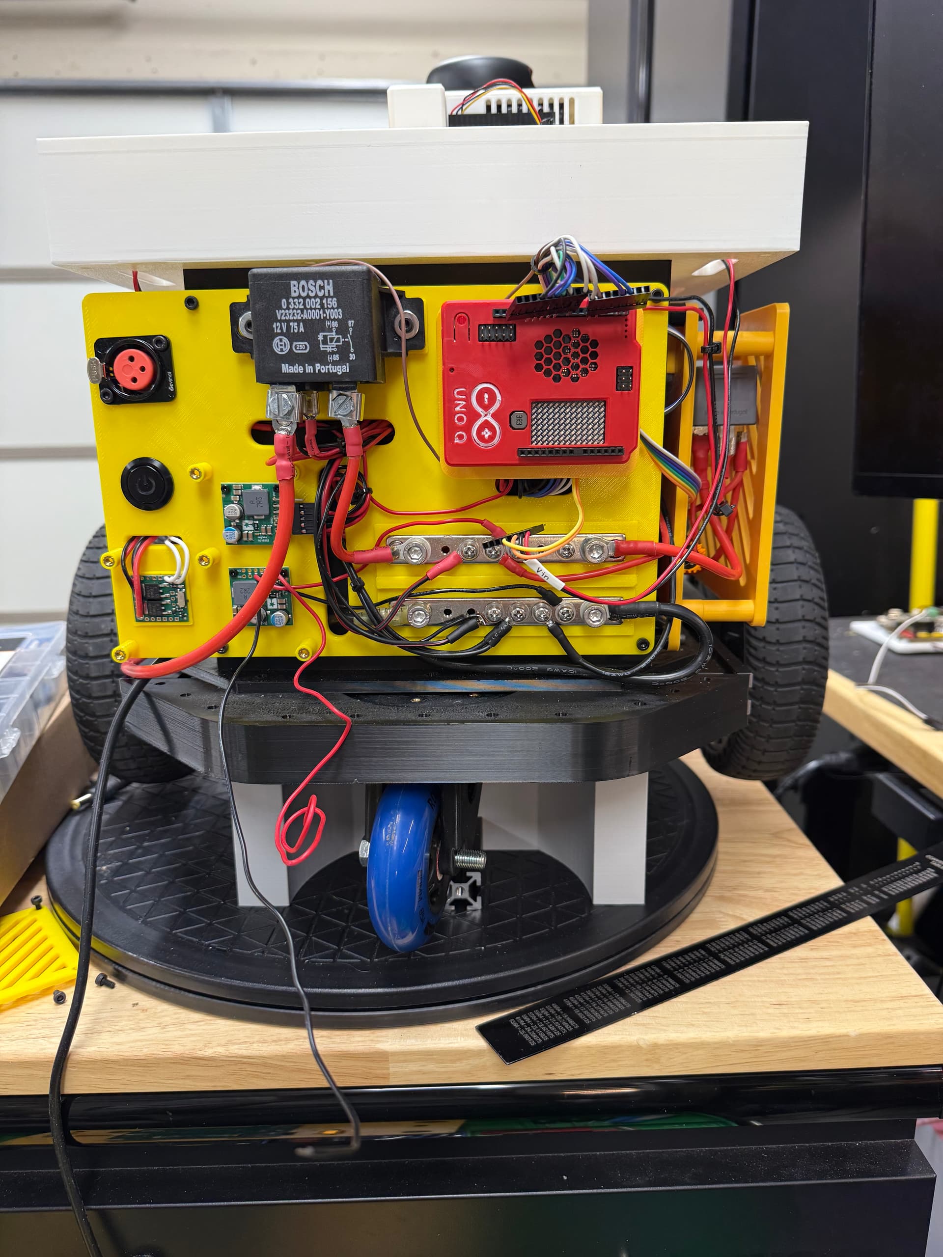
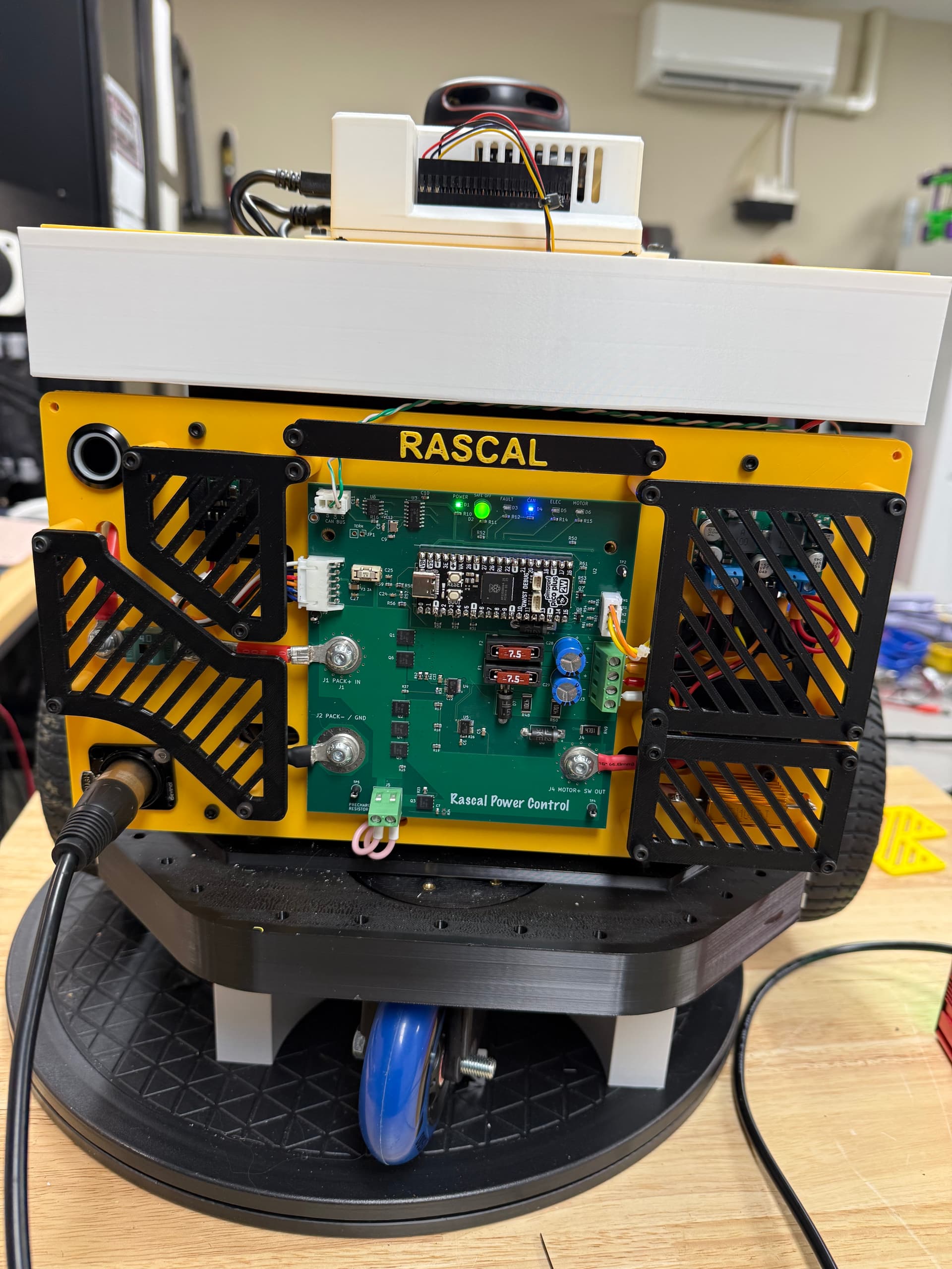
Hi Patrick thank you for your reply. These are some general pictures of the robot. The panel with the bus bars is where the voltage regulators were installed, one is still pictured there. The bus bars are much larger than need as they only provide a connection point for the two regulators. The Odrive controller’s power is provided directly from the power control board. The robot uses 2 Jetson Orin Nano Supers plus, lidar, 3d Camera, ReSpeaker microphone array, CAN bus controllers, a IMU, and a few I2C sensors. As you can see “Rascal” is also a mobile battery. I’m fairly confident that I have caused this issue. I have a couple of ideas as what may have contributed but I would like to hear someone else’s thoughts. In designing the power board I forgot pull down resistors on the gate driver control pins. Both regulators died at the exact same time during reboot of the PICO. I also included a picture of the old power control system which used 3 automotive relays. The regulator fiasco is probably a rookie mistake, but hey my day job is nursing.
Since there are lots of cables, it’s possible that an accidental short circuit might have occurred.
The pictures I shared are after removal of the voltage regulators. The picture with a bunch of wires was the previous power control scheme. There are no short circuits, blown fuses or melted wires. It’s a fairly well built project with few rat’s nests. I sort of wish it had been something like a short circuit. 
Your robot looks great Heather!
Unfortunately, it’s not immediately clear what might have gone wrong to damage the regulators. We got your email, so we will use that to coordinate an RMA so we can look at them.
- Patrick
Hello, just wanted to update on my project. It looks like I have been successful with my version 3 control board. I appreciate the support from Pololu.
2 Likes
We are glad to hear it is going well! Thanks for letting us know.
- Patrick