I’ve been having a good amount of trouble getting the Jrk G2 to work with my current setup. I’m trying to drive a 12v DC motor that has this tachometer for feed back. I seem to get a fairly noisy 12v sine wave centered on 0v. I’ve tried both rectifying the signal then using a capacitor to turn it into an analog signal and rectifying the signal and putting it into an op amp to get a square wave, but with limited success. So I guess in general, I’m looking for advice on integrating with a sensor such as the one I’m forced to work with.
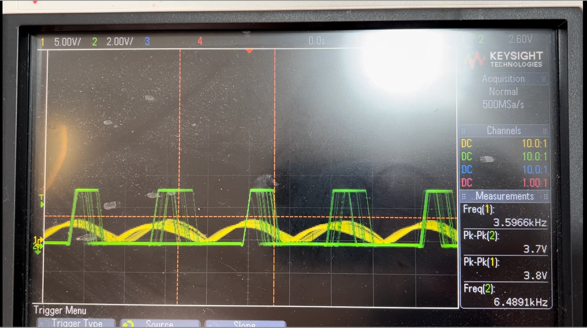
This is a scope view of my most recent attempt to rectify the the wave (yellow), then pass it through an op amp to get a nice square wave.
When using the green signal wired directly to FBT (not 100% sure this is right) and a ground on the negative side of the rectifier, I had a few issues.
When attempting to test the control at a static value, I put a bit of resistance on the motor and the feedback dipped and stayed low, then jumped back up when released. I was under the impression that the controller would up the voltage until the feed back was back at the original location.
It also doesn’t seem like the feedback ever hits the target, I’ve played around with the pid values a lot and I can never get something stable that trends towards the target. Best I can do is get the feed back to stay well above the target and respond proportionally, but I think this is the cause of the problem above.
So I’m not sure if this is a pid tuning issue, or if my signal is not what the JRK expects, or wired in incorrectly.
Could you post a copy of your Jrk G2 settings file? You can save a copy of your settings file from the “File” drop-down menu of the Jrk G2 Configuration Utility.
I recommend carefully reviewing the instructions in the “Setting up frequency feedback” section of the Jrk G2 user’s guide.
In particular, I suggest that you do not invest too much time in tuning your PID coefficients until you have scaled feedback values that are clean and reflect the speed of your motor. In your video, the scaled feedback is very noisy. Also, around 10 seconds into the video, it sounds like the motor speeds up, but at the same time we see that “Scaled feedback” gets closer to 2048. In a properly set up system, scaled feedback values further from 2048 indicate higher speeds, and values closer to 2048 indicate lower speeds.
The Jrk is getting that feedback value by measuring the width of high pulses on the FBT line. However, the pulses I see on the green signal of your oscilloscope look very noisy (i.e. the width is unpredictable), which could explain the noise we are seeing the “Scaled feedback” value. Also, are you sure that the pulse width decreases when the motor speeds up? It might be helpful to see a video or some screenshots from your oscilloscope so we can see what the signal looks like at different speeds.
A good way to test your setup while you are still figuring out how to configure your feedback settings is to follow the recommendations under the “Setting initial PID coefficients” and the “Testing frequency feedback” headers of the user’s guide section that I mentioned earlier.
Ok, just a bit of background that might make my setup that may explain a few things.
First, the motor I’m controlling is actually a piston pump for moving very precise amounts of liquid. So each time the motor spins around it pulls up a plunger and pushes it back down.
Second, the feedback is coming from a pickup next to an 82 tooth gear. So each revolution I will see 82 pulses. This combined with the first point is why I believe I’m getting a bit of a noisy signal. Since the motor has to do a different amount of work to get the piston into different places, I’m betting it causes the noisy signal because it actually is slowing down for parts of the cycle.
Third, the pump is pulled high and I only have the ability to control it’s ground. This is super annoying, but unfortunately I don’t have control over this so I’ve inverted my feedback. This is why at 10 seconds, when I bring the target closer to center, the motor speeds up. Since the voltage comes closer to 0v, the differential to 12 is higher running the motor quicker.
So with that background, I am just trying to see if there is anything else I’m missing to get a more reliable setup. For instance, it would be nice if the power output could be adjusted fast enough to smooth out the variable speed caused by the variable resistance.
As far as setting up the frequency feedback, I’ve got it set to 48 MHz with a divider of 32 to get the 572 Hz to 22.9 kHz which seems to fit the range I see the best. When sweeping the values, my motor goes from ~2 kHz to ~13 kHz on the oscilloscope, (the signal is just about as noisy on each power level, I can get a video of this) so those values seemed best if I’m understanding the guid.
What do you mean when you say you have inverted the feedback? It does not look like you enabled that option in the settings file you posted earlier.
Given the behavior of your sensor, you might try changing the pulse timing polarity setting to measure low pulses instead of the high side. The noise should affect them less as a percentage of their width since they are longer.
You could also try using pulse counting mode instead of pulse timing mode. Pulse counting is typically not as well suited for slower tachometers, but it might give you better results here since you have a lot of signal noise. It also might be easier to confirm that the Jrk’s feedback values make sense with the measurements from your oscilloscope that way.
I think the behavior at the beginning of your first video, where the Jrk is powering the motor at max duty cycle but the motor does not move, goes back to how your pump works:
At the beginning of the video, the motor is stopped so Scaled Feedback = 2048, and Target = 828, so the Jrk thinks it wants to drive the motor in reverse. So the Jrk is driving it in reverse as hard as possible, but that causes the motor to stop because of the unusual wiring. Later in the video, when you bring the target closer to the scaled feedback, the Jrk tries to slow the motor down by making its output pin low for some fraction of the time, but that actually applies power to the motor, causing it to speed up and making the Scaled Feedback shoot down, way below the Target.
The Jrk’s firmware was not designed with this kind of setup in mind and we do not think there is a good way to make it work. Inverting the motor direction just switches which output pin the Jrk will drive high when driving the motor a particular direction. There is a chance you could find something that works okay, but it would probably be in a way where the Jrk does not actually know what it is doing to the motor and the logic and calculations somehow work out anyway.