Trouble using LPS331 pressure sensor with SPI

I’m trying to use multiple LPS331 sensors (pololu.com/catalog/product/2126) with a single Arduino Uno. In order to do this, I need to use SPI instead of I2C. I’m having some trouble with this, however, and can’t determine what’s wrong.

The main problem is that when I try to read data from the sensor, the MISO line will go from high to low, and then to high again, and then won’t be able to go back low when it’s supposed to. Examples:

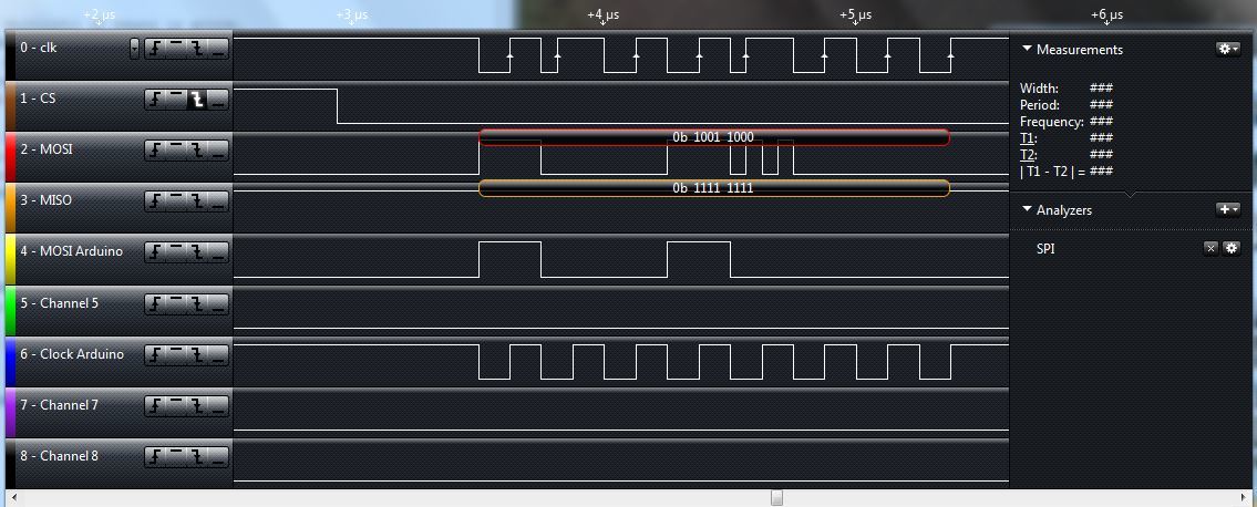
My first example, named “AveragingQueryIncorrect” shows the clock, chip select, MISO, and MOSI at the sensor pins, and the MOSI and clock at the arduino (I’m looking at both places because the wires are long and could contribute to the problem. Note the difference in the clock between the two. I don’t think this is the problem though because it doesn’t seem to get in the way in other situations). I’m reading the value of the RES_CONF registry, which I previously set to 00000010. The MISO line should read 00000010, but instead it outputs 00000011.

In the second example, “WhoAmIQueryIncorrect”, shows the same information with me reading the value of the WHO_AM_I registry, which should always read 10111011. However, instead the sensor is outputting 10111111. I know that the actual stored value is indeed 10111011, because the single sensor works just fine with I2C. That also leads me to believe that the sensor isn’t fundamentally broken or getting incorrect measurements.

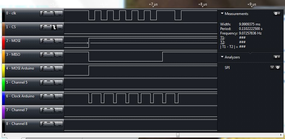
This comes up in a few other places as well. In general it seems like the MISO line will go from HIGH to Low, and then HIGH again, but never back down to low.

There are a few other weird things I encounter that may contribute, but don’t seem to me to be the main problem. The difference between the clock at the sensor and the arduino, which you can see in my first example, could be a problem, although you don’t see it as much in the second example. In addition, sometimes there will be some weird spikes in the MOSI line at the sensor that don’t come from the arduino (see my third example) but as far as I can tell the sensor still interprets these correctly.

In addition, The wires I’m using for the clock, MOSI, power and ground are quite long (~2ft) although at the moment the chip select and MISO wires are much shorter (~8in). Since the shorter wire is what seems to be having the problem, I think it has more to do with the chip than with the wires, but I could be wrong.

What should I do at this point? Would it help to add pull-up or pull-down somewhere? Is the chip irreversibly broken in some way that only affects SPI and not I2C? Is there some way I could get 5 sensors working on a single Arduino board using I2c instead?

Thank you!

Here’s the code that I’m using:

//this is the SPI library- its functions are SPI.xxx
#include <SPI.h>

//enumerate chip select pins, of which there will be 5
const int chipSelectPin0 = 7; //connect sensor0 to Arduino 7

void setup() { //this loop happens once for setup
  Serial.begin(9600); //enable reading out on serial monitor

  SPI.begin(); //start SPI
  
  //Send each bit with the most significant bit first, so
  //if you send the byte 0b11010000, the sensor will see 
  //the 1 first and decide that that is bit 0, the next 1 
  //is bit 1,and the 0 after that is bit 2, etc.
  //Each bit of each register is explained on the data sheet.
  SPI.setBitOrder(MSBFIRST);
  
  //Set the clock speed. Speed is the board speed divided by the number input into the function.
  SPI.setClockDivider(64);
  
  //Set the clock phase and polarity
  SPI.setDataMode(SPI_MODE3);
  
  //make all chip select pins outputs so we can control them
  pinMode(chipSelectPin0, OUTPUT);

//Power down the sensor
 digitalWrite(chipSelectPin0, LOW);
SPI.transfer(0b00100000);
delay(10);
SPI.transfer(0b00000000);
digitalWrite(chipSelectPin0, HIGH);

//average 16 data points in RES_CONF
  digitalWrite(chipSelectPin0, LOW);
  //register location is 0x10, written in bits 2-7 with MSb first
  SPI.transfer(0b00010000); //write to register 0x10
  delay(10);
  SPI.transfer(0b00000010); //tell to average 16 data points
  digitalWrite(chipSelectPin0, HIGH);

delay(100);
  
  //query RES_CONF to make sure it worked
  digitalWrite(chipSelectPin0, LOW);
  SPI.transfer(0b10010000); //read from register 0x10
  delay(10);
  byte avg = SPI.transfer(0xFF); //read back result into variable
  Serial.print("Averaging register ");
  Serial.println(avg, BIN);
  digitalWrite(chipSelectPin0, HIGH);
  
  delay(100);
  
  //This block puts sensor in active mode, sets speed to 25Hz
  digitalWrite(chipSelectPin0, LOW); //turn on SPI for sensor 0
  //Register address is 0x20 (20 in hex), or 100000 in binary.
  //The first byte is telling whether to read/write, and address.
  //The first two numbers are 00 for write, the address follows.
  SPI.transfer(0b00100000); //write to address 0b100000 (0x20)
  //The next byte is the data to be transferred, with bit 0 first.
  //This next byte sets bits 0-3 high on the register CTRL_REG_1,
  //which puts the sensor in active mode and sets speed to 25 Hz
  delay(10);
  SPI.transfer(0b00000000);
  delay(10);
  SPI.transfer(0b11000000); //put sensor in active mode, 25Hz
  digitalWrite(chipSelectPin0, HIGH); //turn off SPI for sensor 0
  
  delay(100);
  
  //query WHO_AM_I
  //This register should read out 0b10111011 if sensor is active.
  digitalWrite(chipSelectPin0, LOW); //turn on SPI for sensor 0
  //register location is 0x0F, or 001111 in binary
  //the 10 in front means we're reading the register
  SPI.transfer(0b10001111); //read from register 0x0F
  delay(10);
  byte who = SPI.transfer(0xFF); //read back result into variable
  Serial.print("Who am I? "); //println is print + enter key
  Serial.println(who, BIN); //print the variable in binary, return
  digitalWrite(chipSelectPin0, HIGH); //turn off SPI for sensor 0
  
  delay(100);
  
  //query CTRL_REG_1
  digitalWrite(chipSelectPin0, LOW);
  SPI.transfer(0b10100000); //read from register 0x20
  delay(10);
  byte ctrl = SPI.transfer(0xFF); //read back result into variable
  Serial.print("CTRL_REG_1 ");
  Serial.println(ctrl, BIN);
  digitalWrite(chipSelectPin0, HIGH);
  
  delay(100);
 
}


Hello.

Could you tell me more about your setup? What is connected to your Arduino, and how do you have everything connected? Pictures or a diagram would help. Are you able to get just one LPS331AP sensor working with the Arduino using either SPI or I2C?

Please note, the SDO and CS pins do not have level shifters on them, and applying 5V to those lines can break the sensor. I see that in your code you call digitalWrite(chipSelectPin0, HIGH). Did you have an appropriate level shifter on that line or did 5V get applied to that pin?

- Jeremy

Thanks for the reply Jeremy!

I can’t get you a picture right now, but I can describe it. If you’d like a picture, I could take one and put it up tomorrow.

As I am testing it, the sensor is the only thing being used with the arduino, which itself is attached by USB to my computer. The Vin goes to the 3.3V supply, and GND goes to ground. SDI is connected to Arduino 11, SDO to Arduino 12, and SPC to Arduino 13. CS is connected to Arduino 7. We don’t have any level shifting, so SDO and CS were definitely getting 5V.

However, it does seem to work still with I2C, as far as I can tell. I don’t exactly have a perfect reference to be sure, but the values are close to what we’ve seen in the past and they seem to change reasonably with increased or decreased pressure.

Will applying the 5V break it for good, or only while the 5V is applied? Is only the SPI part broken, which would explain why I2C still works?

An alternative question, one thing we considered was trying to use 5 sensors with I2C by combining all of the clock and SDA wires and powering the chip off an on as a sort of crude chip select (this is with a different sensor than the one the examples are from). It seemed to work in the sense that we could turn the sensors on and off and sensible data was being transmitted and received, but the sensor would only send back 0’s. We’d rather use SPI the proper way, of course, but I’m curious if you know why this doesn’t work and if it’s at all possible.

Thanks for your help! We definitely didn’t know that we couldn’t apply 5V to SDO or CS, so that explains a lot.

-Amos

By applying 5V to those pins, it is possible that just those pins were damaged (or maybe you were lucky and nothing was damaged). It’s difficult to say what will happen if you apply 5V to pins that are not 5V tolerant.

Do you have another LPS331AP sensor that has had 5V applied to its non-5V-tolerant pins? You should not have to use a level shifter on the CS pin because it has an internal pull-up to 3.3V, so you can drive it low when you want it to be low and you can let it float (i.e. make the control pin an input) when you want it to be high.

The Arduino should be treating the SDO pin as an input, so you shouldn’t need a level-shifter on that, either (but you should probably verify that it is indeed floating when SPI is enabled before you actually connect it to the sensor).

If you do have another LPS331AP, maybe your first step should be to try a new sensor with SDO disconnected from your Arduino. You can still use your logic analyzer to monitor what the sensor is trying to send back to the Arduino and determine if that makes sense.

I am a little confused by this sentence, as the “sensible data was being … received” statement seems to contradict “the sensor would only send back 0’s”. I do not know of any reason why what you are suggesting wouldn’t work. I think you should reduce it to the simplest case and incrementally increase complexity:

  1. Connect a single sensor via I2C, power it from an I/O line, and try to read data. Does this work?
  2. If yes, connect a second sensor’s I2C lines to the bus while leaving it unpowered. Are you still able to get good readings from the first sensor?
  3. If yes, connect the second sensor’s VIN pin to a separate I/O line and try to communicate with it over I2C while the first sensor is unpowered.

In this manner, keep adding sensors to the system until either something fails or you have a complete working system.

- Jeremy

Hi Jeremy,

Thanks for your help. Not putting 5V into the CS seems to have the sensors working much more reliably. We got some new sensors and tested them out and they all worked well on a breadboard with SPI. However, now we’re running into a new problem.

I’ve attached a picture of our setup. We’re using the LPS331 breakout board with long wires (a little over 2ft) connected to an Arduino Uno. When we use shorter wires (4 inches), everything works fine, but when we go to longer wires, we only get 1’s back from the sensor. However, if we ground the chip select, it starts working again, and then stops if it’s disconnected from ground. We thought this might indicate that the CS is not being driven low enough, but when we probed it with a multimeter it would go down to around 20mV.

We were originally using 22 gauge solid core wire, but since it worked with a shorter wire we thought it might be a problem with capacitance so we switched to 24 gauge stranded speaker wire, but it seems to make no difference.

Any idea what might be causing this or how to fix it? Thanks!


It sounds like your issue might be a bad connection rather than the wires being to long. Could you double check all your connections? I suspect there is a bad ground. If you do not find anything wrong, maybe you can try replacing the short wires one at a time with the long wires and see which one causes it to stop working.

- Jeremy

Hi Jeremy,

We checked connections and a few other things. We ended up getting it to work by wrapping the wires in aluminum foil, so it seems like it was a noise problem. The long wires, specifically the CS, were picking up signals in the air and acting as a small current source, which raised the voltage at the CS pin on the sensor even though the voltage was low and it was grounded at the arduino.

Thanks for your help!

Thanks for letting us know. I am glad you got it working.

- Jeremy