Has a transfer function or frequency response function been developed for the Tamiya 72101 Gear Head Motor set sold in Pololu? I’m adding a Kalman filter to my project (gbot90 balancing robot, link below) and have equations for the gbot, but not the motors. Help is very much appreciated.
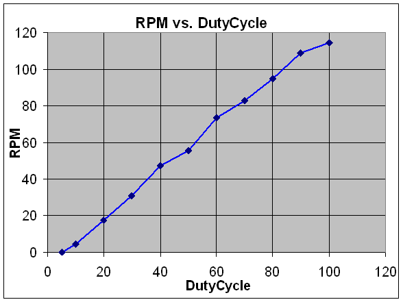
Okay, I assembled an IR encoder to measure RPM on the Tamiya 72101 motors controlled by the Dual VNH2SP30 Motor Driver. I sent a PWM signal with constant duty-cycle equal to 100% and measured 114 RPM - the motor was unloaded. The Tamiya spec says 242 RPM at no load. I made several measurements at different duty cycles, and I found a linear trend. See enclosed plot. Can Pololu verify the measured 114 RPM or the 242 RPM spec? Thanks.
I just applied 7V to one, and I was getting about four rotations per second. Are you sure you don’t have a factor of 2 missing somewhere in your encoder-based results? Four times a second isn’t that fast, so you should be able to just look at the output shaft and count four rotations every second.
Yes, I screwed up. I checked my spreadsheet equation and found that it had twice the number of encoder segments than reality. So my measured RPM is in fact close to the spec. Thanks very much for checking. Now I can proceed with measuring the response to a step input. From what I’ve gathered, I think the motors will be too responsive for my RPM measuring setup. I’ll start with an encoder disk with lots of segments and see how that goes. Appreciate your quick response.
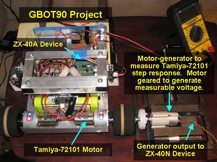
I finally got a chance to characterize the Tamiya-72101 motors for my gbot90 project. The gbot90 is a self balancing robot with PID feedback control:
I want to characterize the motors to improve the feedback control system. Right now I assume the motors respond instantaneously, so the goal is to measure the motor transfer function to quantify the RPM response to throttle input. The throttle is PWM duty cycle.
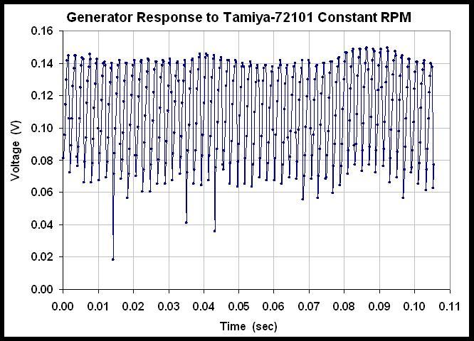
To characterize the motors, I input a step function (0 duty cycle to 100% duty cycle in ~0sec) and measured the RPM response vs. time. I learned the hard way that using IR encoders was not practical because the Tamiya-72101 motors were too responsive. So instead, I coupled a separate geared motor/generator (with low mechanical resistance) to the Tamiya shaft. It was geared to generate adequate voltage. The output was routed to a separate ZX-40N device to measure RPM response in terms of voltage. See attached image for setup:
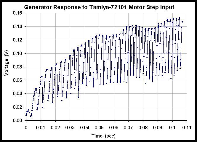
The ZX-40N zbasic code has two basic arrays: one for time (via GetElapsedMicroTime) and the other for generator voltage (via GetADC). I set the array size to 400 elements and that nearly used up all the available RAM, but was enough to capture the step response shown in attached image #2. The response signature was very repeatable after 5 trials.
In short, it shows the Tamiya motor reach full RPM in about ~0.09sec. I was surprised to see how oscillatory the responses would be, but I learned that it’s an artifact of the generator. I verified this by running the Tamiya motor at constant RPM (100% duty cycle) and recorded the response. See attached image #3. Even at constant RPM, the generator shows a oscillatory response with a clear mean and consistent amplitude likely correlated to generator RPM. Bottom line is that enough data was gathered to fair out a decent transfer function. I suppose some capacitors on the generator will tame the oscillations?