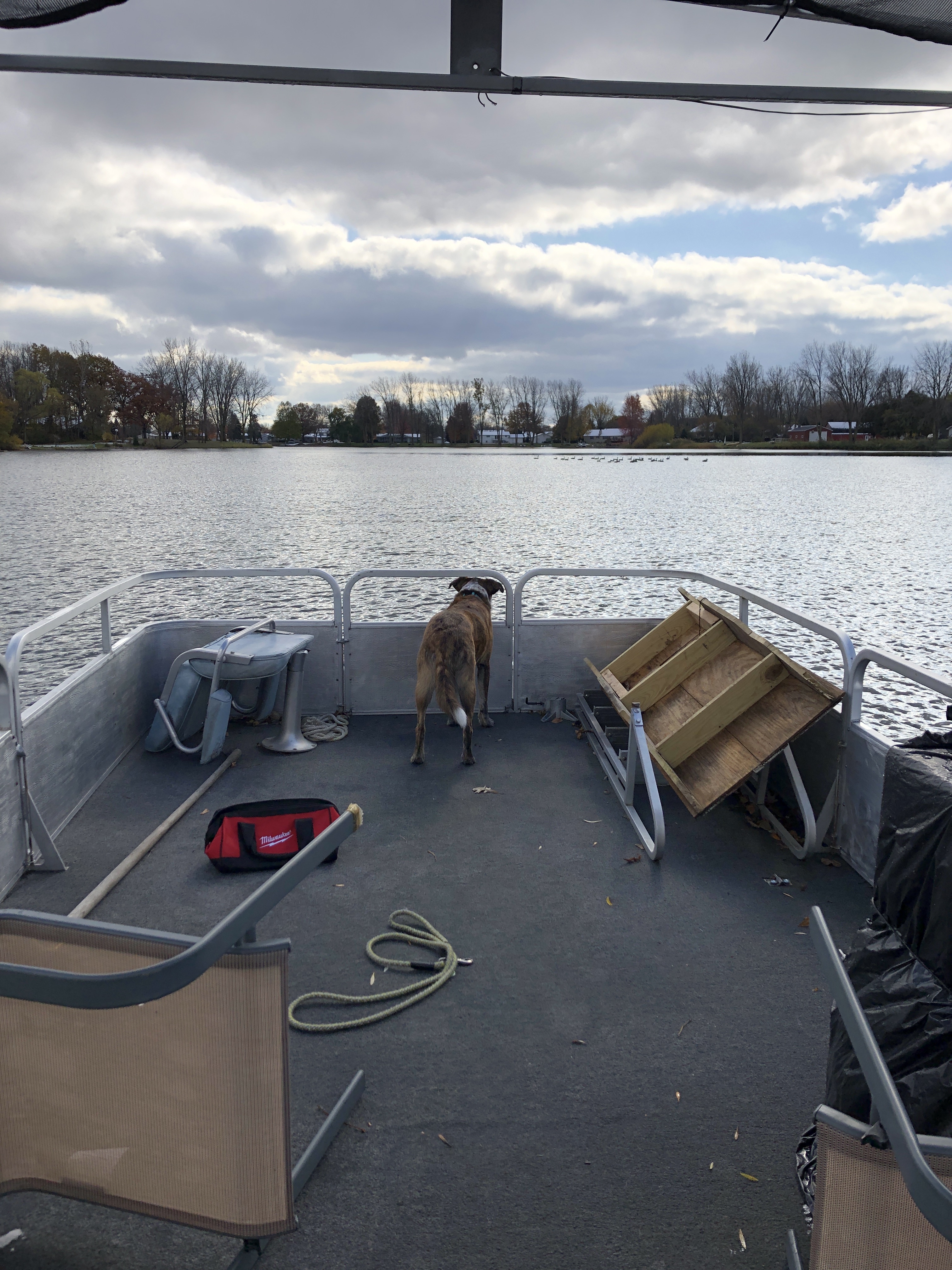
I have the great fortune of living on a small private lake and being the proud new owner of a very old, but partially restored 24’ pontoon boat. The lake and the boat are about cruising and enjoying time with up to a dozen of our closest friends. It is essentially a floating backyard deck. The lake is restricted to electric only, but this does not mean we are immune to one-ups-man-ship. Many of the Jones’ have brand new boats with electric outboards on 48v systems that total well north of $20k. I plan to compete with size and electronic wizardry where I cannot with dollars. The very sturdy deck of my boat is adorned with lawn chairs and patio furniture, but has plenty of room for fun.
Propulsion is a single, transom mounted, tiller adjusted minn Kota 12v 55lb thrust trolling motor. So far I have piloted from a bench at the back of the boat, but dream of residing behind the helm. Steering is a simple cable drive, but throttle will take more doing. I do plan to add a second matching motor and control setup. This will allow for differential steering.
A “throttle “ will be mounted at the helm that uses a potentiometer to send signals to an Arduino. The Arduino will communicate with a Tic249 driving a very small NEMA 8 stepper mounted in the motor control housing and is connected to the potentiometer the motor uses for speed control. The stepper is dual shaft, so the front can be controlled externally by a knob when the fancy electronics fail.
So far I have all the parts I think I need and have modeled the interior of the control housing in fusion360. The cap that will hold the stepper is nearing workable. I also have most of the raw code done for the Arduino side and have it mostly working on the breadboard.
Future enhancements may include the second motor, a linear actuator to provide motor lift and an electronics upgrade to include gps and Bluetooth for app control or, more interesting, location and heading hold.
Thanks for sharing your project! It sounds like you have a workable plan. You might need to take into account the potential losses that could result from the longer lines needed to reach your helm. I suggest doing some testing to see if it is going to be an issue sooner rather than later.
Good luck, we would love to hear how it turns out!
@Derrill, thank you for the kind comments on my project. I am glad you brought up the distance involved. It has been a concern as I have yet to try to communicate over any type of distance previously. I expect it will be about 15ft and planned to do some experimentation. That is part of the reason I was planning to do an Arduino from the start as I was concerned running leads from the Tic to a potentiometer that far away would not work. I am also curious to see if I can do I2C or will need to do straight serial. I2C would be easier as I plan to add an additional motor and Tic, though I did see where I can do serial with 2 Tic boards.
I suspect I²C might be a problem at 15’, but TTL serial might be okay depending on the electrical noise in the area. You should probably consider shielded cable for your connection as a first step.
First experiment was just using a little over 15ft of Cat5e. I used one pair for power and ground and another for tx/rx. I would expect there to be more “noise” when in operation. If twisted pair is sufficient for this I could conceivably even use a 15+ ft pre-made Cat7 as that is still relatively inexpensive and is certainly shielded.
I also tried with I2C, but it was very erratic. Again, this is using only Cat5e. The Serial connection seemed to work pretty good, next I will try the method of addressing two Tic boards using serial. That is really the only reason I wanted to use I2C.
I have looked a bit at Your Differential signaling boards. Very interesting idea to expand I2C to much greater distances.