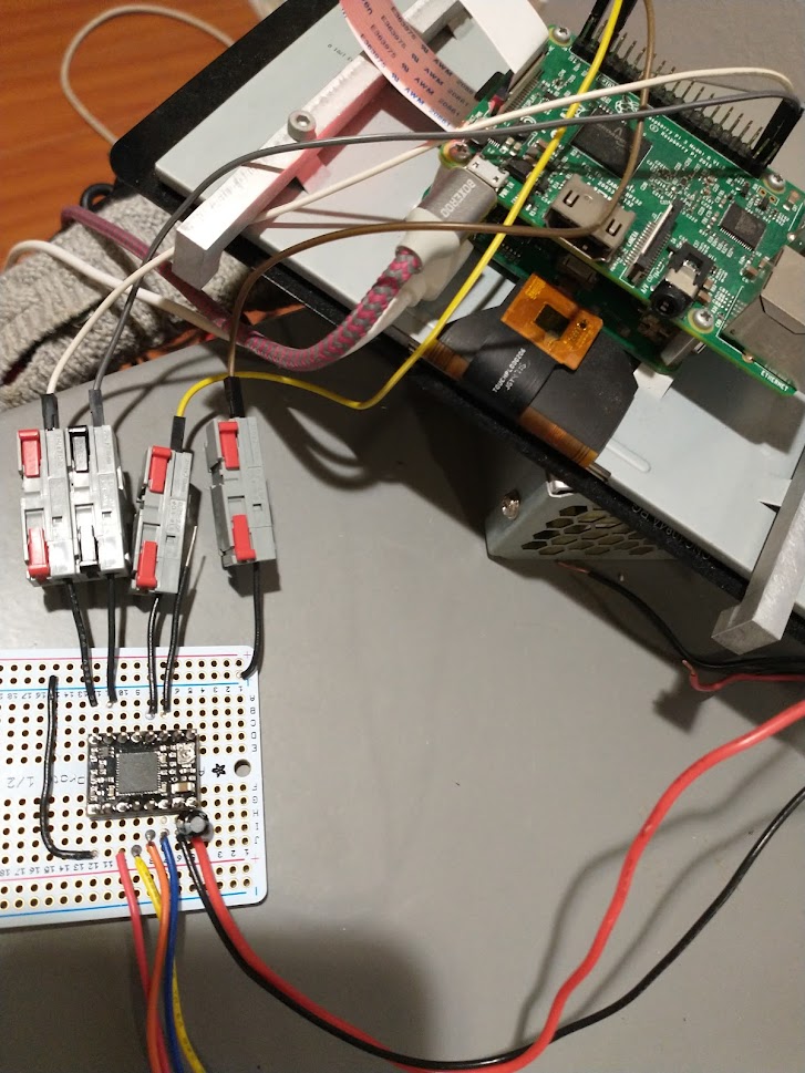
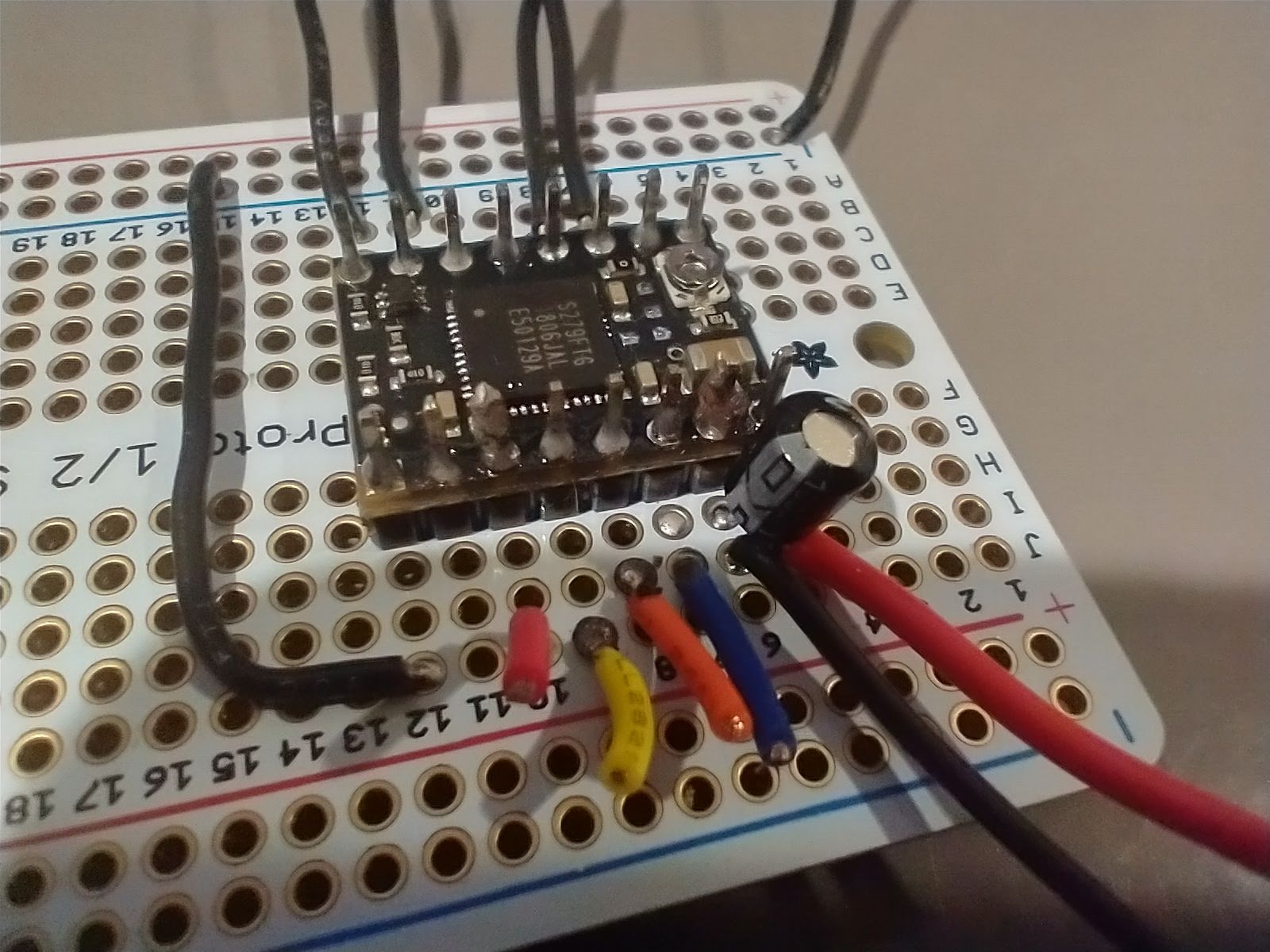
Unsure what might be the problem- I’ve done some searching online, but keep finding myself with a zero reading for the VREF. Attaching an image below (apologies, its a bit sloppy).
I have the motor controller connected to a 12V, 10A power supply, and confirmed with the multimeter that the board is receiving 12V. DMODE2 is connected on HIGH, at 5V (also confirmed). DIR and STEP are connected to GPIO pins 20 and 21 (no program is running). The motor controls are soldered into place, but unplugged from the motor.
Hoping for some troubleshooting advice. I had some responsiveness when measuring Voltage from the unfused, 10A max port of the multimeter, but this measurement was at 1.7 mV and fluctuated quite wildly. Outside of this, readings have been a pretty consistent zero. I have tried measuring from the screw location to ground, in most instances.
Update: I had a spare motor control board and re-tried the VREF reading. All appears to be working properly- the board pictured might be DOA. I’d consider this topic closed.
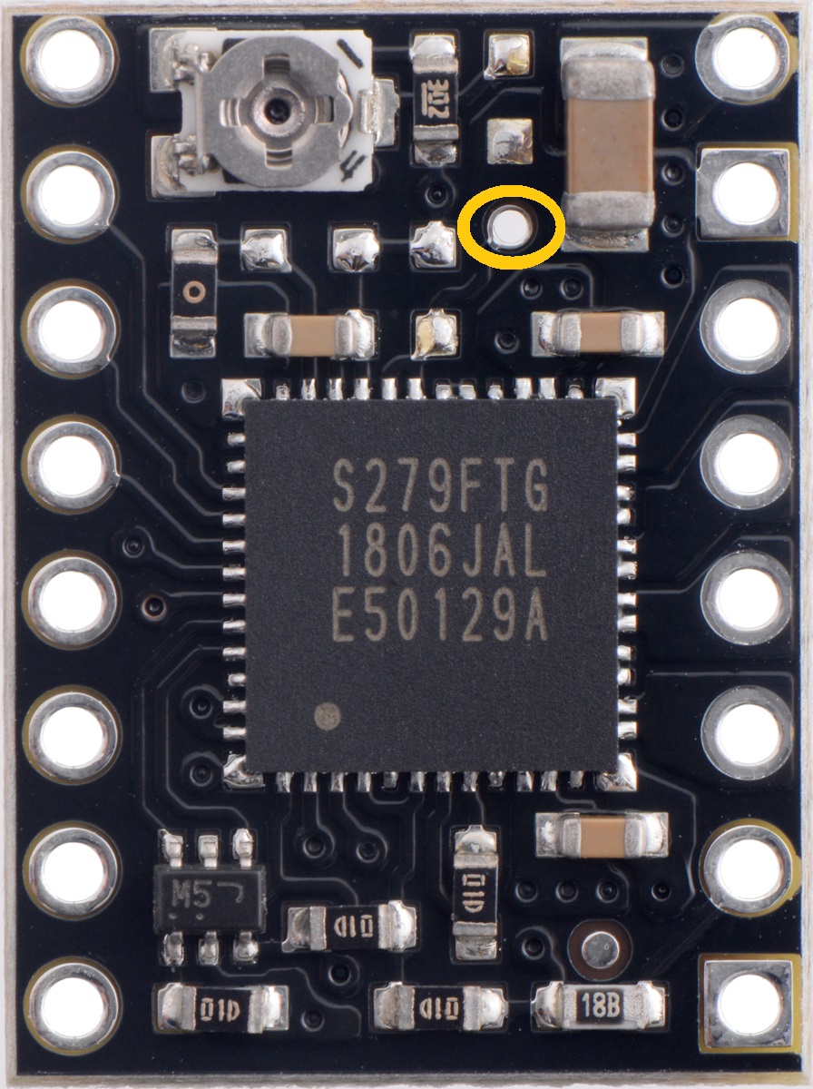
I’m sorry to hear that one of your TB67S279FTG compact carriers is not working. We would like to do some troubleshooting. Were you ever able to get a valid reading of VREF from it? From an email you also sent us it sounds like you have a few of those boards. Can you confirm if the others are working, and if they are being used in the same kind of setup? Could you also post closeup pictures that show the show the solder joints on both top and bottom of your protoboard? Please also try measuring the voltage from the VREF via circled in yellow in this picture:
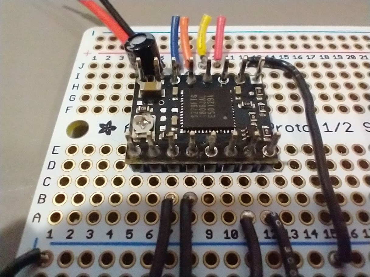
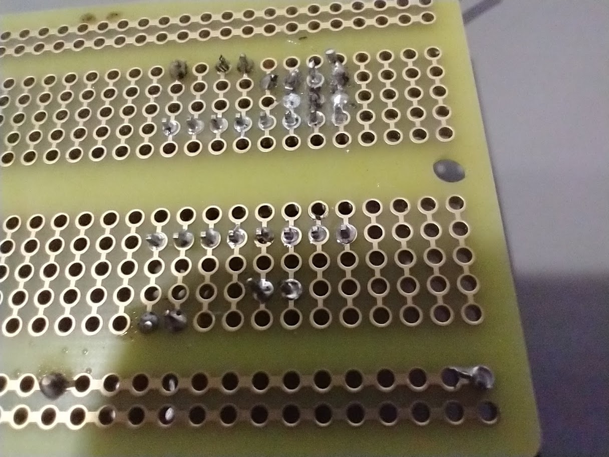
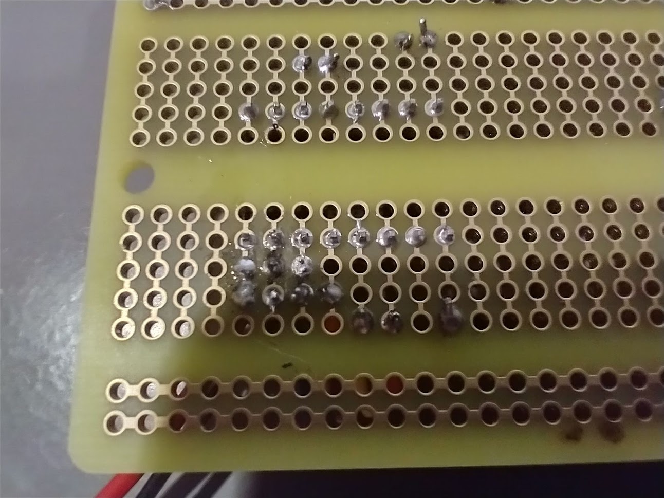
Hey Claire, thanks for the response- it’d be great to see if there was a working fix to the issue. I never was able to get a VREF from this board, though I did test out the other two boards I purchased and was able to get a VREF from these. Testing the unresponsive board again now, I was also unable to measure VREF from the circle as pictured. Will attach images of the solder joints of this board- Some of the bottom joints look a bit messy, though I was able to verify with the multimeter continuity test that nothing was overlapping.
Lots of the solder joints in your pictures look like they are not properly wetted and might need more solder. Ideally you want the solder to fill the entire metal pad around each hole and form a volcano like shape up the pin. Could you try touching up the soldering (particularly for VMOT and GND)? This Adafruit soldering guide might be a helpful reference:
Hey Claire, thanks for your time. I got the chance to touch things up tonight- still not reading. I also did reverify that GND and VMOT were receiving the full voltage
Could you post some updated pictures? Have you been giving a high signal to any of the DMODE pins during testing? If not, could you try that? Have you tested your other two drivers with motors?
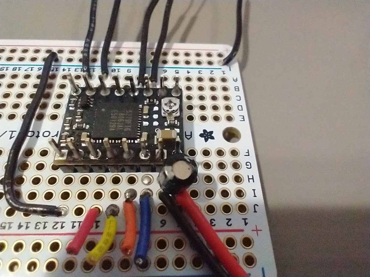
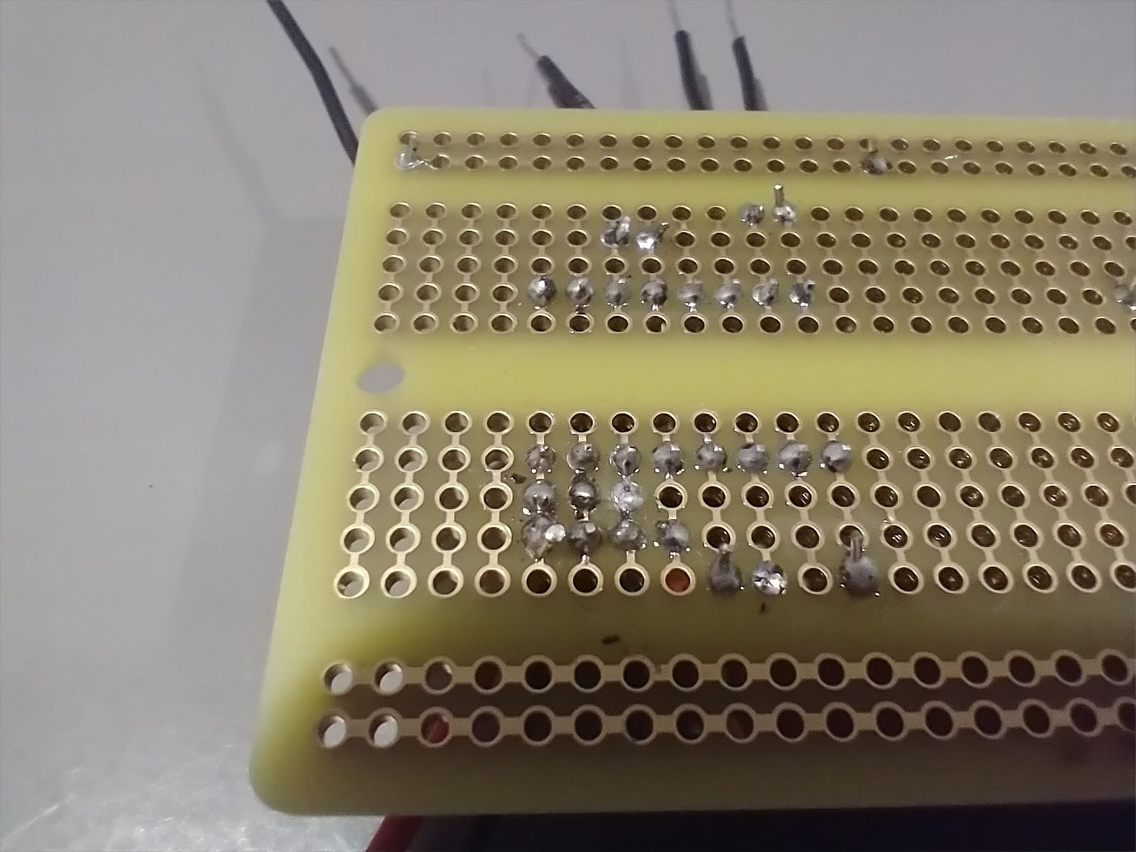
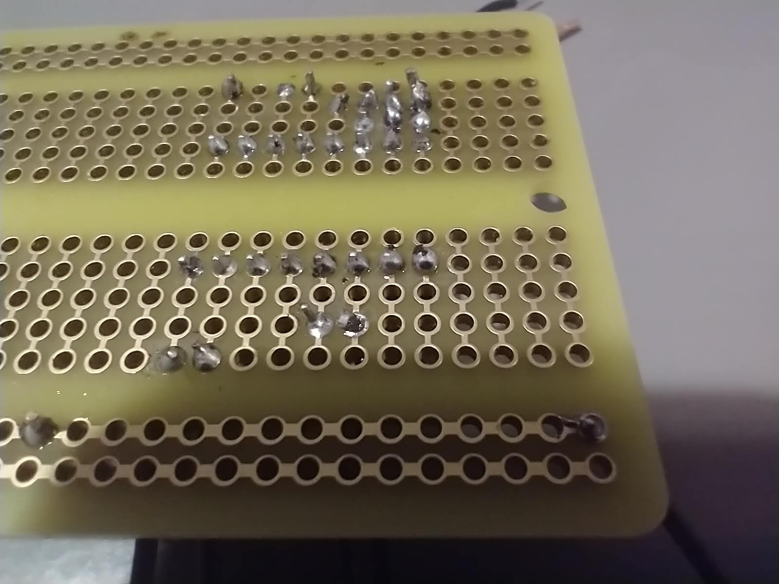
Hey Claire, I got some time tonight to look at things more closely- it was actually the soldering on the top of the board that was lacking (when I last messaged you, I had just touched up only the bottom side of the board and ran the test, like a fool). The board works just fine Thanks for the troubleshooting! Attaching pictures, just encase someone stumbles upon this thread looking for a resolution.