
Hi everyone,
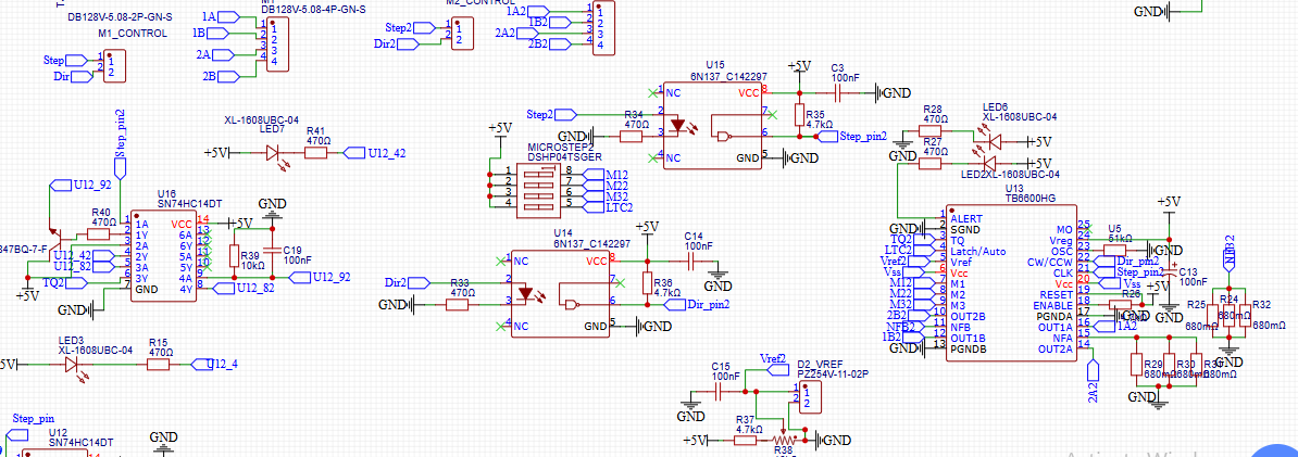
I’m working on a university project involving two stepper motor control, and I’ve chosen to use the TB6600 stepper driver for its reliability and ease of use. As part of the project, I’ve designed a custom schematic using the TB6600, but after proceeding with PCB fabrication, the I am having voltage reading in motor coils, but motor is not moving(NEMA 23). I’d really appreciate it if someone with more experience could take a look and provide feedback.
I’m particularly concerned about whether:
- My logic level connections are appropriate.
- I’ve handled the enable/reset pins is correct or no.
- The motor power supply section is adequately protected.
- Any passive components (e.g., current sense resistors, flyback diodes, etc.) are missing or incorrectly chosen.
I’ve attached my schematic below.
Could someone please let me know if there are any issues or risks in my design?
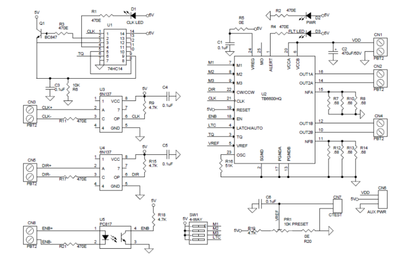
If anyone has a known-good reference schematic for the TB6600 that I could use for comparison or inspiration, that would also be incredibly helpful.
Thanks in advance for your support – I really value the expertise in this forum!
Best regards,
Towfiq