I’m working on a new project, one just for myself, where I need to be able to have 9V of fairly low-current power switched from an RC receiver. Poking through your catalog, I found two parts (#1210 RC Switch with Small Low-Side MOSFET, and #791 Adjustable Boost Regulator) that appear to fit the bill. The RC receiver will get power from a 4xAA battery pack, which is more than enough to drive the servos I’ll have attached.
The question I have is whether I can use #1210 and #791 this way (sorry for stealing these graphics out of your catalog):
Essentially this uses the same power and ground that accompany the RC channel that is operating the switch to provide the load power. The load should never exceed 150mA at 9V.
One other question: I’m planning to use this to power a video transmitter. I’ve run into problems in the past when sharing power sources between servos and transmitters. I’m planning to add a common mode choke to the output of this to clean up the power. But is that necessary, or is the output stage of the #791 regulator already filtered? (Anything I can do to shave weight helps. Even something as small as a choke.)
Thanks!
Tom
P.S. AAAARGH! Ok, when looking at the above diagram, assume I can read a datasheet and actually get the unregulated input and regulated output on the correct pins of the regulator board. Duh. Feeling a little dorky at the moment for getting that backward.
The setup in your diagram should work (with the exception of the regulator’s input and output connections being swapped, as you already mentioned). Keep in mind that you will also need to provide VCC to the RC switch, which needs to be between 2 and 5.5 V.
There are some capacitors on the output of the regulator, so you might not need to add any extra filtering, but you will probably have to experiment to find out for sure.
From the diagram on the RC switch page, it looks like the board can pick up Vcc from the RC cable. Is this true? Or do I need to jumper to the Vcc pin on the opposite side of the board as well?
I guess I have no excuse now not to experiment and get this working. Looking forward to it.
VCC is not connected to either VRC or the load supply by default, though you can use the jumpers on the back of the board to connect it to either. If you are using 4 rechargeable AA batteries (nominally 1.2 V each for a total of 4.8 V), that should work fine for VCC, though be aware that their voltage can be significantly higher when they are freshly charged.
Makes sense. (I finally read the rest of the product description, and found the picture of the two sets of jumper pads.)
So here’s yet another pair of questions for you:
If I jumper both the VCC=Load Supply and VCC=VRC pads, will this also tie VRC to Vload? (I’m guessing this is a yes.)
Do all of these share a common ground? Or would I still need to jumper the RC ground pin to the load ground pin in order to make this work?
I lied. Just one more question:
I use NiMH batteries on this. So far the highest charge I’ve been able to get per cell is 1.32V, which puts me at 5.28V without any losses. Flying too close to the sun?
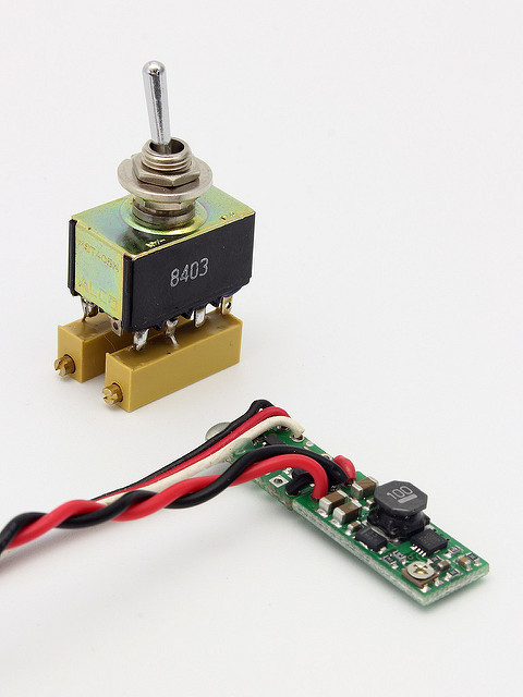
The switch in the upper left is installed into the ground-side RC transmitter. The two 5k pots soldered onto the switch let me dial in two set points I can toggle between. The fourth set of poles on that switch are used to control power to a video receiver and monitor.
The RC switch and variable boost regulator go on the vehicle. The pair of boards plugs into the channel on the RC receiver that’s tied to the quad pole switch. When the switch is flipped on, the RC switch also turns on. The Vbatt and Gnd lines from the RC channel are switched, and fed into the boost regulator. What comes out the twisted black and red wires is regulated power that can be fed to a video transmitter.
The net effect is that I have a switch on my RC transmitter. When it’s flipped off, all the video hardware is off. When it’s flipped on, all the video hardware turns on, both on the ground and in the air. This is a nice battery saver for those times when you really don’t need the video feedback from a remotely operated vehicle. Or in this case, from a remotely operated camera mount.