
Hi folks,
I’ve had good success using Pololu step-down regulators in conjunction with 7.4 V LiSOCl2 batteries over the past few years to power the Iridium satellite transceivers in my instrumentation deployed in the Arctic.
With both SparkFun and Adafruit almost universally adopting the AP2112 LDO regulator for all of their microcontrollers, I’m now faced with a 6 V input voltage restriction. This has led me to explore the possibility of bypassing the AP2112 and powering the 3.3 V rail directly using a D36V6F3 3.3V, 600mA Step-Down Voltage Regulator (manually replacing the LDO isn’t desirable).
I’ve been running some tests over the past couple of weeks, and the D36V6F3 appears to be doing a good job of powering my circuit. When enabled, the current draw of the regulator at 7.4 V is measured to be ~64 uA (0.5 mW), which is comparable to the AP2112. The overall draw of the circuit shoudn’t exceed 50 mA, so voltage dropouts aren’t a concern.
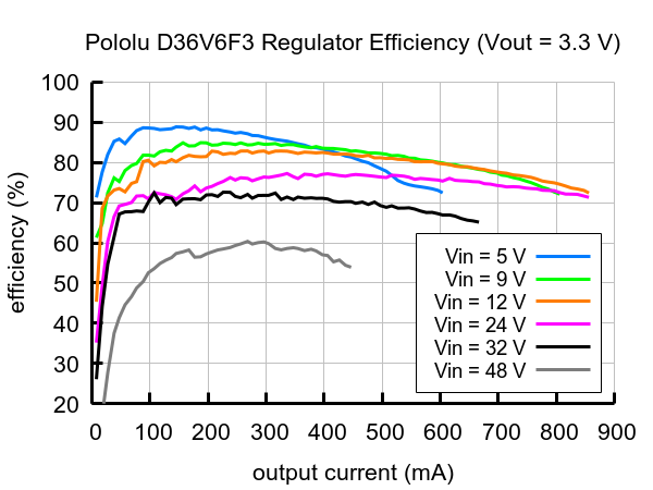
My main query pertains to efficiency. I am cognizant of the fact the D36V6F3 is not intended for extremely low quiescent loads (my circuit has a sleep current of ~50 uA). Based on the provided graph, it seems that the step-down regulator should be between 60-70% efficient under the circumstances.
My questions are:
- Would the D36V6F3 be a feasible alternative to the AP2112?
- If so, is there any way to quantify how much power is actually wasted?
Cheers,
Adam