
Hi,
I’m a beginner in robot based project. I found a line follower project tutorial by Mr.Arnabdas https://www.youtube.com/watch?v=7-ju19RMWlw.
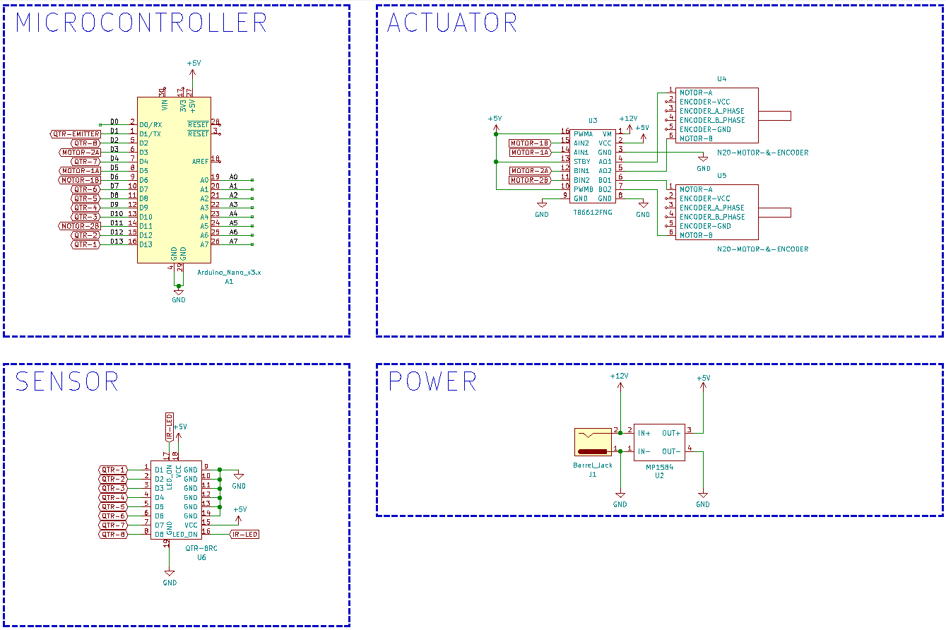
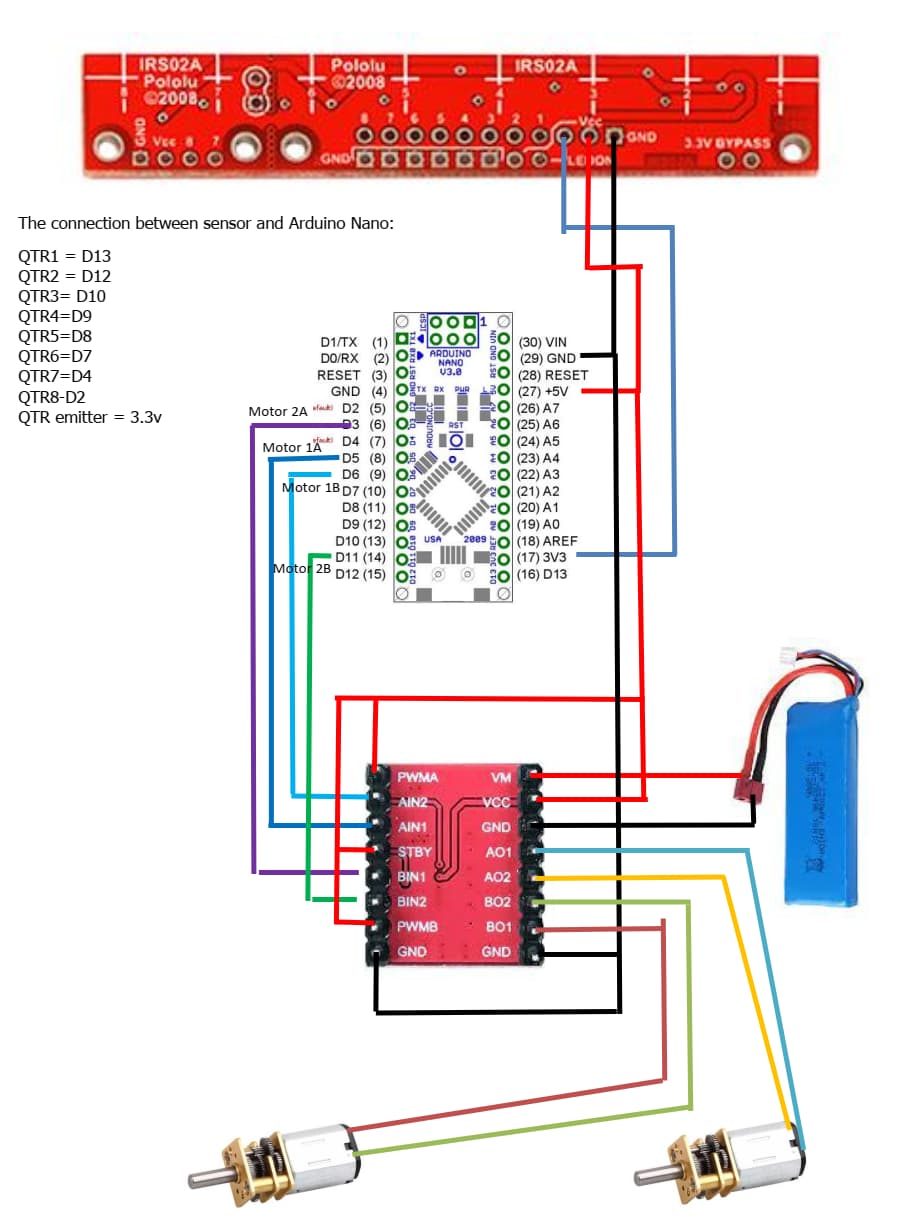
He gave me a diagram and the code for the project. I need help regarding to connection between the components in the project since I got confused with the diagram and how to connect QTR-8RC properly. Here I have attach the schematic diagram that I got from him and a diagram that I used to connect all the components.
I hope some one could tell me what I did wrong in this project. Here is my achievement so far (literally) https://youtu.be/-Q1MztrDLj8.
Here is the schematic diagram:
And here is what I was understood from the diagram (connection that I made to my project):
And here is the code given by him:
/*
* Arduino NANO - QTR-8RC - PID Line Follower Robot V1
*
* Created: 14-07-2021 10:44:58 PM
* Author : Arnab Kumar Das
* Website: http://www.ArnabKumarDas.com/
*/

#include <avr/io.h>
#include "avr_gpio.h"
#include "avr_motor.h"
#include "avr_qtr.h"

#define LFR_MAX_MOTOR_SPEED 255    /**< Sets the Maximum PWM Duty Cycle for Line Follower Robot 0=0% 255=100% */

void LFR_Initialize()
{
    /**< Sets the Pin Mapping for QTR-8RC Sensor ; Change the Individual Pin Macros in avr_qtr.h */
  uint8_t QTR_Pins[] = {QTR_1_PIN, QTR_2_PIN, QTR_3_PIN, QTR_4_PIN, QTR_5_PIN, QTR_6_PIN, QTR_7_PIN, QTR_8_PIN};
  QTR_Init(QTR_Pins, QTR_EMITTER_PIN);    /**< Initializes the QTR-8RC Sensor */
  Motor_Init();                           /**< Initializes the Motors */
  _delay_ms(2000);                        /**< Pause ; Useful to Align the Robot Manually if Outside the Line */
}

void LFR_Calibrate()
{
  Motor_SetSpeed(90, -90);      /**< Rotates the Robot */
  for(uint8_t i=0; i<40; i++)   /**< Calibrate the QTR-8RC Sensor */
  {
    QTR_CalibrateSensor(QTR_EMITTERS_ON);
    _delay_ms(20);
  }
  Motor_SetSpeed(0,0);          /**< Stops the Robot */
  _delay_ms(500);
  Motor_SetSpeed(-90, 90);      /**< Rotates the Robot */
  for(uint8_t i=0; i<80; i++)   /**< Calibrate the QTR-8RC Sensor */
  {
    QTR_CalibrateSensor(QTR_EMITTERS_ON);
    _delay_ms(20);
  }
  Motor_SetSpeed(0,0);          /**< Stops the Robot */
  _delay_ms(500);
  Motor_SetSpeed(90, -90);      /**< Rotates the Robot */
  for(uint8_t i=0; i<40; i++)   /**< Calibrate the QTR-8RC Sensor */
  {
    QTR_CalibrateSensor(QTR_EMITTERS_ON);
    _delay_ms(20);
  }
  Motor_SetSpeed(0,0);          /**< Stops the Robot */
  _delay_ms(2000);              /**< Pause ; Useful to Realign the Robot Manually if Outside the Line */
}


int main()
{
  uint16_t LFR_SensorValue[8];       /**< Array to Save Raw IR Sensor values of QTR-8RC */
  uint16_t LFR_Position = 0;         /**< Variable to Save the QTR-8RC Sensor Position */
  int16_t  LFR_Proportional = 0;     /**< Variable to Save the Proportional Output of PID Control Algorithm */
  int16_t  LFR_LastProportional = 0; /**< Variable to Save the Previous Proportional Output of PID Control Algorithm */
  int16_t  LFR_Derivative = 0;       /**< Variable to Save the Derivative Output of PID Control Algorithm */
  int64_t  LFR_Integral = 0;         /**< Variable to Save the Integral Output of PID Control Algorithm */
  int16_t  LFR_ControlOutput = 0;    /**< Variable to Save the Final Control Output of PID Control Algorithm */

  LFR_Initialize();                  /**< Function to Initialize all Peripherals */
  LFR_Calibrate();                   /**< Function to Calibrate QTR-8RC Sensor */

  while(1)
  {
    LFR_Position = QTR_ReadLine(LFR_SensorValue, QTR_EMITTERS_ON);    /**< Reads the QTR-8RC Line Sensor to Get the Line Position */
    LFR_Proportional = LFR_Position - QTR_LINE_MID_VALUE;             /**< Computes the Proportional Output of PID Control Algorithm */
    LFR_Derivative = LFR_Proportional - LFR_LastProportional;         /**< Computes the Derivative Output of PID Control Algorithm */
    LFR_Integral += LFR_Proportional;                                 /**< Computes the Integral Output of PID Control Algorithm */
    LFR_LastProportional = LFR_Proportional;                          /**< Saves the Old Proportional Output of PID Control Algorithm */

    LFR_ControlOutput = LFR_Proportional/10 + LFR_Integral/10000 + LFR_Derivative*3/2;    /**< Computes the Final Control Output of PID Control Algorithm */

    if(LFR_ControlOutput > LFR_MAX_MOTOR_SPEED)
    {
      LFR_ControlOutput = LFR_MAX_MOTOR_SPEED;    /**< Keeps The Motor Speed in Limit */
    }
    if(LFR_ControlOutput < -LFR_MAX_MOTOR_SPEED)
    {
      LFR_ControlOutput = -LFR_MAX_MOTOR_SPEED;    /**< Keeps The Motor Speed in Limit */
    }

    if(LFR_ControlOutput < 0)
    {
      Motor_SetSpeed(LFR_MAX_MOTOR_SPEED + LFR_ControlOutput, LFR_MAX_MOTOR_SPEED);    /**< Drives the Motor According to the Control Output */
    }
    else
    {
      Motor_SetSpeed(LFR_MAX_MOTOR_SPEED, LFR_MAX_MOTOR_SPEED - LFR_ControlOutput);    /**< Drives the Motor According to the Control Output */
    }
  }
}
I hope someone can help me on this project and sorry for my bad English. Thanks.