hi, i am trying to build a line following robot. i am using arduino rbbb(due, atmega 328) and i have 4 aa batteries 1000 mah for power supply… everything is working except the fact that my qtr sensor doesn’t read the black line correctly… i am using a a black line of 2,3 cm width on a white surface… the problem is that the first three sensors(0,1,2) are working just fine but the the last three (3,4,5) seem to change values simultaneously… for example when the robot is at the left of the line on the white surface all sensors have values near 35… when i move slightly the robot to the right then sensor1 sees the black line and it’s is value is 900+… this goes on for the second and the third sensor. when the 4th sensor sees the black line it seems that the fifth and sixth sensor see it as well, when in reality they are above the white surface… when i move it more to the right and only the sixth sensor is above the black line and five and four are above the white surface the values of the sixth sensor are very near, almost the same, to the values of the other sensors (near 30)… my sensors are connected to analog inputs of the arduino from 0-5… the ground of the arduino connects to the ground of the qtr board and to the ground of the batteries… the qtr vcc connects to arduino 5V pin… i have LEDOn connected to digital pin 10 and i have set it to HIGH… all connection seem right and i have checked them many times but i cannot see where the problem is… my baud rate is 57600 and i have changed it in the example programs (raw and callibrated values) from the qtr library… i am sendind my data to the pc wirelessly via a wixel.
please help! any idea may be very helpull!! thanx…
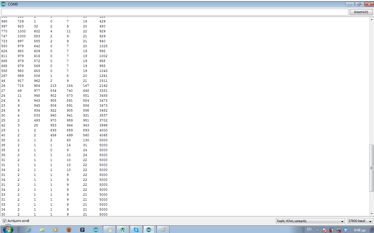
these are the raw values using the code from the qtr library… they show what happens when i move the robot from left to right…
at the 1st picture values from 4,5,6 seem to be correct but on the 2nd picture sensors 5,6 have values near the values from 4th sensor…
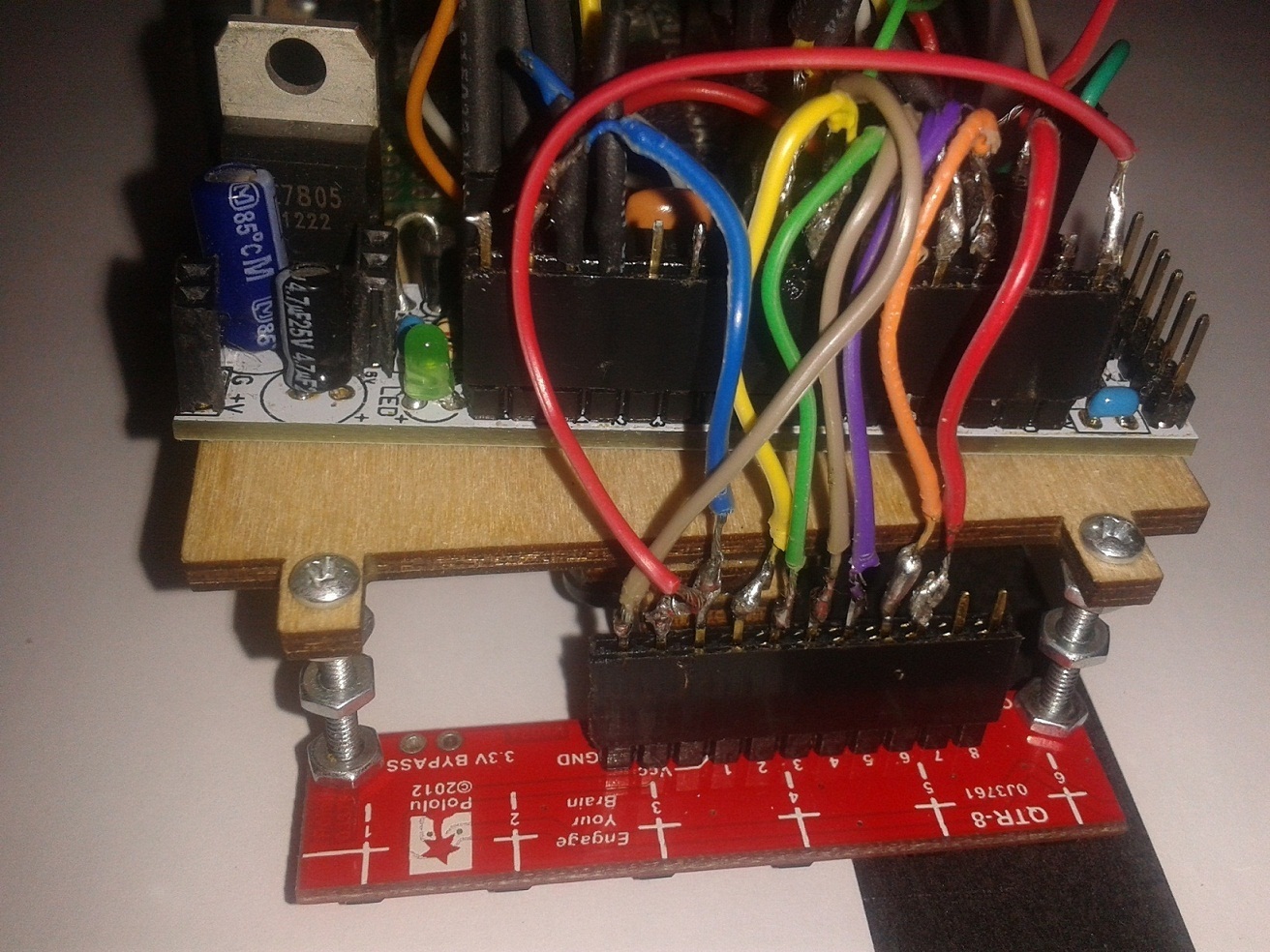
Thank you for the detailed setup description and pictures. Some of your solder joints look very suspect, and the behavior sounds like you have a connection problem.
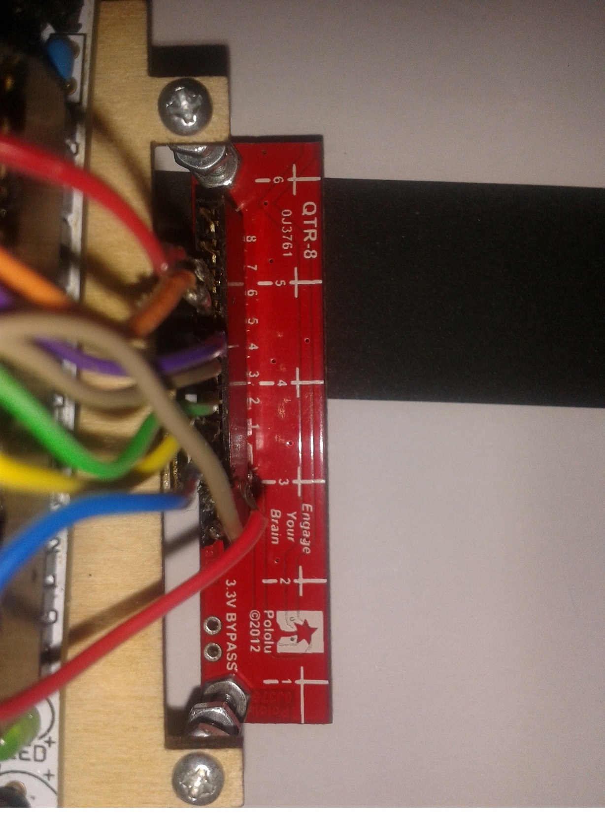
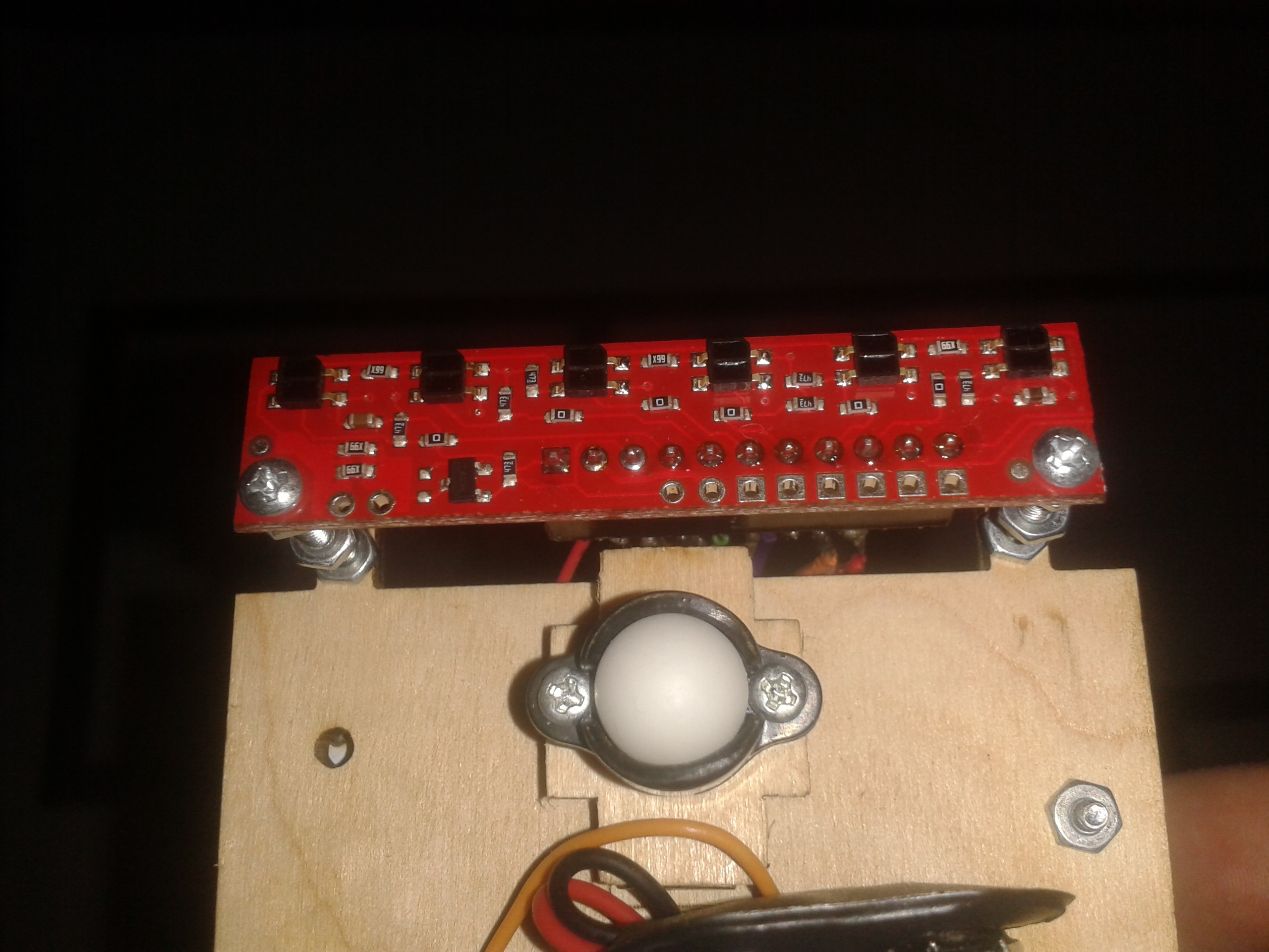
Can you post the code you are running? Also, can you post a picture that shows the other side of the QTR sensor? Lastly, can you use a multimeter to measure the voltage on the Arduino’s 5V output pin?
this is the code i’m using… it’s almost the same with the callibrated_values example but i have changed the emitter_pin and the baud rate… i also have in comments the code to read the values from the analog inputs but when i do that almost every value is above 700 constantly… i also used the raw_values example with the same changes. sensors 5 and 6 follow the values of sensor 4 and i am thinking that some electrical short is causing it… my solder joints are not so good, i know it and i am going to change them, but they are not shorted anywhere… lastly i do not have a multimeter at the time so i cannot test the 5V output…
thank you for your reply!!
#include <QTRSensors.h>
#define NUM_SENSORS             6  // number of sensors used
#define NUM_SAMPLES_PER_SENSOR  4  // average 4 analog samples per sensor reading
#define EMITTER_PIN             10  // emitter is controlled by digital pin 2

// sensors 0 through 5 are connected to analog inputs 0 through 5, respectively
QTRSensorsAnalog qtra((unsigned char[]) {0, 1, 2, 3, 4, 5},
  NUM_SENSORS, NUM_SAMPLES_PER_SENSOR, EMITTER_PIN);
unsigned int sensorValues[NUM_SENSORS];

//  const int analogValue0=A0;
//  const int analogValue1=A1;
//  const int analogValue2=A2;
//  const int analogValue3=A3;
//  const int analogValue4=A4;
//  const int analogValue5=A5;
//
//  int analog0,analog1,analog2,analog3,analog4,analog5=0;


void setup()
{

  Serial.begin(57600);

  Serial.begin(57600);

  Serial.println("");

  pinMode(EMITTER_PIN,OUTPUT);

  digitalWrite(EMITTER_PIN,HIGH);

//    pinMode(analogValue0,INPUT);
//    pinMode(analogValue1,INPUT);
//    pinMode(analogValue2,INPUT);
//    pinMode(analogValue3,INPUT);
//    pinMode(analogValue4,INPUT);
//    pinMode(analogValue5,INPUT);


  delay(500);
  pinMode(13, OUTPUT);
  digitalWrite(13, HIGH);    // turn on Arduino's LED to indicate we are in calibration mode
  for (int i = 0; i < 400; i++)  // make the calibration take about 10 seconds
  {
    qtra.calibrate();       // reads all sensors 10 times at 2.5 ms per six sensors (i.e. ~25 ms per call)
  }
  digitalWrite(13, LOW);     // turn off Arduino's LED to indicate we are through with calibration

  // print the calibration minimum values measured when emitters were on
  for (int i = 0; i < NUM_SENSORS; i++)
  {
    Serial.print(qtra.calibratedMinimumOn[i]);
    Serial.print(' ');
  }
  Serial.println();

  // print the calibration maximum values measured when emitters were on
  for (int i = 0; i < NUM_SENSORS; i++)
  {
    Serial.print(qtra.calibratedMaximumOn[i]);
    Serial.print(' ');
  }
  Serial.println();
  Serial.println();
  delay(1000);
}


void loop()
{
  // read calibrated sensor values and obtain a measure of the line position from 0 to 5000
  // To get raw sensor values, call:
  //  qtra.read(sensorValues); instead of unsigned int position = qtra.readLine(sensorValues);
  unsigned int position = qtra.readLine(sensorValues);

  // print the sensor values as numbers from 0 to 1000, where 0 means maximum reflectance and
  // 1000 means minimum reflectance, followed by the line position
  for (unsigned char i = 0; i < NUM_SENSORS; i++)
  {
    Serial.print(sensorValues[i]);
    Serial.print('\t');
  }

//    analog0=analogRead(analogValue0);
//    analog1=analogRead(analogValue1);
//    analog2=analogRead(analogValue2);
//    analog3=analogRead(analogValue3);
//    analog4=analogRead(analogValue4);
//    analog5=analogRead(analogValue5);
//
//    Serial.print("analog0= ");
//    Serial.println(analog0);
//
//    Serial.print("analog1= ");
//    Serial.println(analog1);
//
//    Serial.print("analog2= ");
//    Serial.println(analog2);
//
//    Serial.print("analog3= ");
//    Serial.println(analog3);
//
//    Serial.print("analog4= ");
//    Serial.println(analog4);
//
//    Serial.print("analog5= ");
//    Serial.println(analog5);
  //Serial.println(); // uncomment this line if you are using raw values
  Serial.println(position); // comment this line out if you are using raw values

  delay(250);
}
I think you should try to simplify things so we can get a better idea of what might be going wrong. My suspicion is that sensors 5 and 6 do not have a good connection to your Arduino, so the readings you get on those pins are being heavily influenced by the reading of sensor 4. There are a few ways we can test for this. First, I would like you to just try a basic program that calls analogRead() on the six sensor pins to get their raw values (don’t use the QTR library, and don’t do anything with the emitter pin). Can you post that program along with its output as you slide the array over a black line?
That is a very strong indication that analog pins 5 and 6 are not electrically connected to the QTR array. If you disable the pull-ups and read the sensors in a different orders, you will probably read values for 5 and 6 that approximately match the values of whatever sensor you read right before them.
I think at this point you should invest in a multimeter (they are not very expensive, and they are pretty much an essential tool if you are going to be working with electronics like this). I suggest you disconnect the QTR sensor array from the Arduino entirely and just use a multimeter to see what the voltages are on the channels as you pass the array over the line. If you probe at various points, you should be able to determine where your connection is broken.