I bought one of these units a few days ago from one of your distributors here in Sweden. I also bought an accelerometer that works fine.
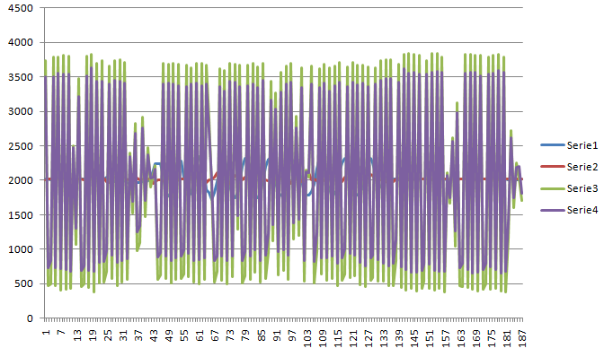
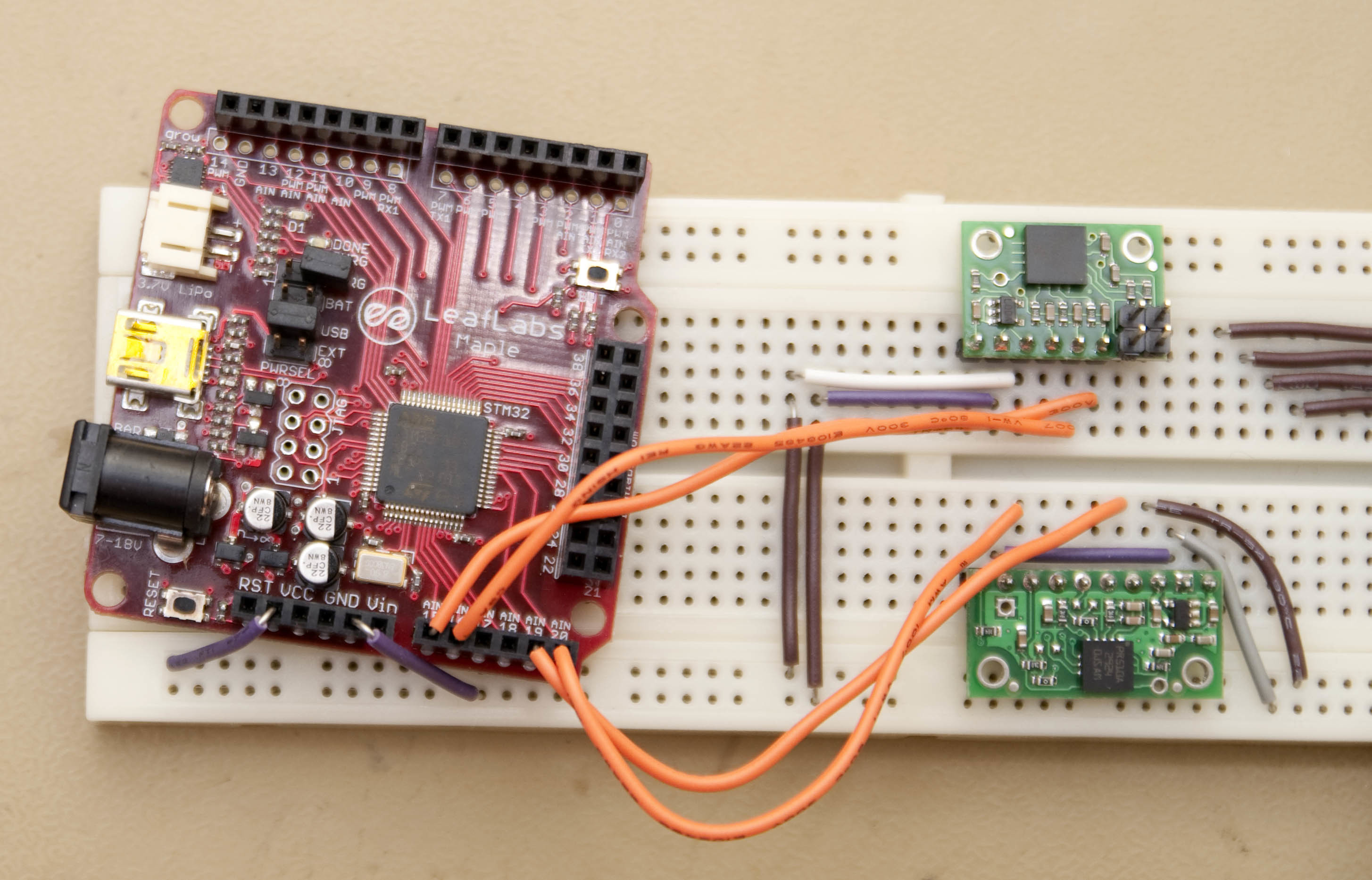
The analog output is very strange going from max to min all the time. I got a replacement unit from the shop but that has the same problem so I don’t think it is a HW problem with the unit. I also tested to connect it to an Arduino but it showed the same problem. See the attached photo of my setup and sensor output.
Any suggestion on what the problem might be? I must miss something simple.
#define ACC_X_PIN 15
#define ACC_Y_PIN 16

#define GYRO_X_PIN 19
#define GYRO_Y_PIN 20


void setup() {
  pinMode(ACC_Y_PIN, INPUT_ANALOG);
  pinMode(ACC_X_PIN, INPUT_ANALOG);
  pinMode(GYRO_Y_PIN, INPUT_ANALOG);
  pinMode(GYRO_X_PIN, INPUT_ANALOG);
}

void loop() {
  // read the analog input into a variable:
  int gyroXValue = analogRead(GYRO_X_PIN);
  int gyroYValue = analogRead(GYRO_Y_PIN);


  int accXValue = analogRead(ACC_X_PIN);
  int accYValue = analogRead(ACC_Y_PIN);


  // print the result:
  SerialUSB.print(accXValue);
  SerialUSB.print("\t");
  SerialUSB.print(accYValue);
  SerialUSB.print("\t");
  SerialUSB.print(gyroXValue);
  SerialUSB.print("\t");
  SerialUSB.println(gyroYValue);


  delay(100);
}
It looks like you are using both the accelerometer and gyro incorrectly, but it seems the accelerometer is handling it more gracefully. If the VCC rail of your Arduino is 5V, you are potentially destroying the boards by connecting 5V to the 3.3V pins of both boards. You should be using the VIN pins, which are inputs for on-board 3.3V voltage regulators.
I will double check with a volt meter but this is not an Arduino, this is a Maple (leaflabs.com/devices/maple/) that runs on 3.3V. And when I tested it with the Arduino I connected it to the 3.3V output.
Thank you for the clarification; it’s a little confusing when you talk about connecting it to an “Arduino” in your opening post and show a graph with an unlabeled Y axis that looks potentially like it’s in millivolts. I assume now that they are 12-bit ADC readings from the Maple?
I’ve never heard of behavior like this from these gyros, and your getting the same results from two separate units implies that there is something wrong with the way you’re connecting them or reading them. Do you have access to an oscilloscope? It would be helpful to remove the Maple from the system to better determine what is at fault.
Does analogRead have an internal delay to compensate for the A2D input mux switching? If not, then maybe that is a reason for the odd values? The previous input may have an influence on the input being sampled.
I now found the problem. It was a rookie misstake I should have found erlier… The wires on the experimental board I use for power/ground are divided in two parts so the gyro was not powered (and not grounded either). The A2D read values as if it was completely disconnected.

 The wires on the experimental board I use for power/ground are divided in two parts so the gyro was not powered (and not grounded either). The A2D read values as if it was completely disconnected.