Hello I am trying to control multiple stepper motors inside of a split flap display.
The display has all the existing electronics and technology but I have been unable to control it with the RS232 protocol that I suspected it used. The display is a Funkwerk split flap display from Koln airport.
I am now trying to control each letter individually with the existing Stepper motor on each letter, I have taken one letter section apart and need some help to identify how the motor is best controlled.
The power supply for the system uses 42VAC and 9VDC.
I am trying to see what kind of power supply I can use for stepper motor from inside the letter.
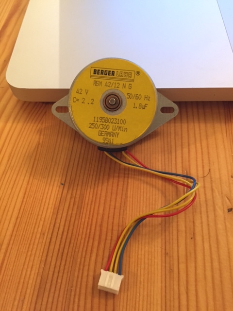
Stepper Motor
I believe it is Bi-Polar.
It does say “42 V” But wondering if I can use a different voltage.
The Motor has 4 wires
Red
Yellow
Yellow
Blue
The resistance between the Red and 1st Yellow is 518 and Blue and 2nd Yellow is also 518, and any others is Over range.
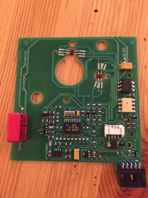
PCB for Stepper, trying to figure out what kind of sensors are being used? Inferred maybe?
Any Help greatly appreciated.
Thank you
That is not a stepper motor, although it is very similar in construction to a stepper. It is a synchronous AC motor and requires a 1.8 - 2.2 uF high voltage AC capacitor in series with one of the coils to shift the phase 90 degrees (the big pink cap on the lower right of the controller board in the picture).
One option is to supply 42 VAC, 50-60 Hz and 9 VDC, then try to figure out how the board works. You can also use the motor without a controller. Just supply about 40 VAC, using the cap, and the motor shaft will rotate 250-300 rpm depending on the power line frequency.
The motor will probably work as a stepper motor (without the capacitor), but you would need to create your own high voltage driver.
Awesome thanks for your knowledge, If I can control it as a stepper do you think I would be able to use this?
DRV8825 Stepper Motor Driver Carrier, High Current:
https://www.pololu.com/product/2133/specs
With 42VDC? bipolar?
Try it and let us know. I would avoid approaching the upper voltage limit (45 V) of the DRV8825 too closely. Try 35 volts first, bipolar configuration of course. The step size may be pretty large.