Hi, I bought 4 units of the Stepper Motor Driver 36v4.
Connected properly I had them working without load. But as soon as I connected the motor (2.3V @ 3A NEMA24), the driver stopped working and no signal of what happened.
The V5 output is off, I have it powering the IOREF pin. No response from the driver, no 5V regulation output…
One of the drivers has a short-circuit between RESET and GND.
Any ideas of what could happen? - Someone had any similar situation?
Thanks in advance!
Hello.
Can you send me pictures of your boards and how you had everything connected when they failed along with more information about your stepper motor (including a datasheet if possible) and power supply? How were you testing the drivers, and did they fail all at once or one at a time? Did you use one of the examples from our Arduino library?
- Patrick
Hello Patrick.
I’m not using the Arduino library, I’m using a PSoC CY8CKIT-059. The drivers fail one at a time.
I have wired:
V5 to IOREF (Jumper on the driver)
STALL to P0.7
SLEEP to P0.6
DIR to P0.5
STEP to P0.1
SDATO to P0.0
SDATI to P15.5
SCS to P2.4
SCLK to P2.3
I’m powering the driver with a 24V @ 11A power supply; a DC-DC Buck converter to power the PSoC at 5.1V.
I managed to set it up to work without load (No motor connected), and I saw the “stepping-voltage” at AOUTs and BOUTs, so the driver was working. It was configured to see it working at low speed, half-step with a 5Hz STEP frequency and enable motor (Modifying CTRL register). All the other registers by default, no changes.
As soon as I connected the motor (no motion perceived, not noises or any weird behavior), the driver went to STALL and FLT (both bits went to 0V; then the driver didn’t respond anymore and the V5 output were to off, so no IOREF signal to pulling-up the STALL or SLEEP pins were working… Even when the motor was disconnected. Tried with other driver, same result…
The Stepper motor is a 60BYG250-102:
- Bipolar
- 2.3V
- 3A current/phase
- 1.8° step angle
- 0.75 ohm Resistance/phase
- 2.4mH Inductance/phase
- 3.5Nm Holding Torque
- 1000gcm2 Rotor inertia
Thank you for all the information. Since you only modified the CTRL register, it sounds like you did not alter the driver’s default current limit. As we note on the product page, it is important to set it to something appropriate for both your stepper motor and the driver before activating the outputs; otherwise, when the driver powers up, the current limit setting defaults to the maximum (~18 A), which is way more than the driver and your stepper motor can handle. So right now, that seems to be a likely cause of damage to your drivers.
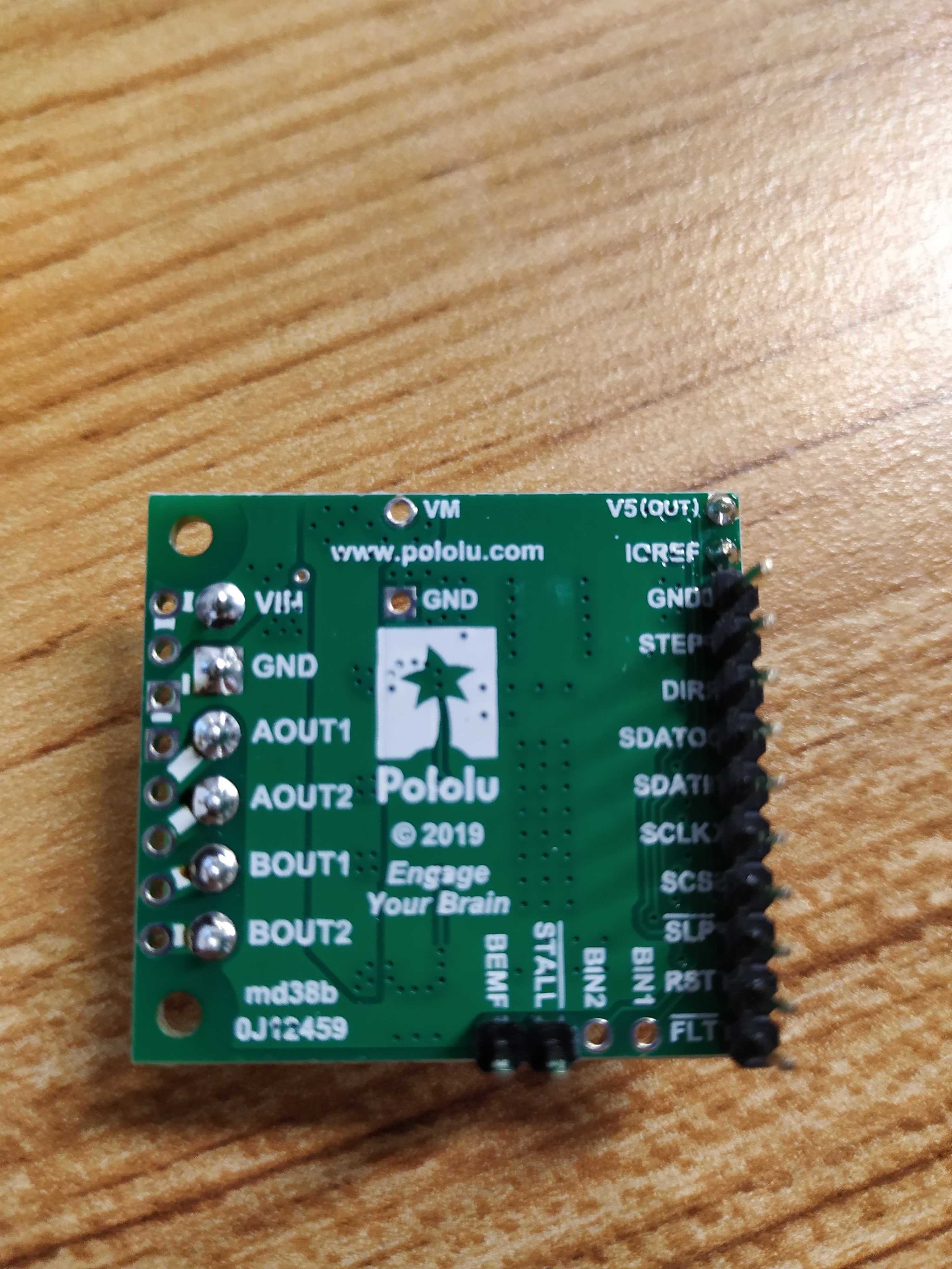
Could you power one of your boards and measure the voltage between VM and GND? Also, it would still be useful if you could post some pictures showing the boards, your solder connections, and how everything was connected during your tests so I can look for any signs of damage or other potential sources of problems.
- Patrick
Hi Patrick.
The voltage between VM and GND still 24Vdc. Is the V5 output who is dead and I believe the whole driver…
I understand the issue, do you think the motor was also damaged, the PSoC?
Here some pictures of one of the affected drivers and our “main” protoboard; I tested all the wiring and connections are OK and in good shape.
Do you think all the issue was about the current setup? - or probably something else happened? - One concern is that the second driver that stops working was connected after the first failure but this time without the motor connected and still stop working, maybe the PSoC also was affected…
Did you change the motor wiring while the circuit was powered up?
Doing so will instantly destroy the driver.
The current setup is probably the cause of failure for at least the drivers that you powered and connected to your motor. If you changed your motor connections while the driver was powered, like Jim said, that could also have damaged the drivers.
Can you clarify what you did with your second motor driver? Was it ever connected to a motor?
I am not sure if your microcontroller would have been damaged, so I would recommend separately testing it out to determine if it is okay before you try to do anything else with it.
- Patrick
Hi Jim. With the module powered off I connected the motor, turn on, no motion, no nothing, it fails… After it went to fail I just powered off, disconnect the motor and run it again without load, the driver didn’t answered back…
No hot handling of any connection or wiring.
Patrick.
The second driver apparently is OK… I’m very ashamed and embarrassed with this, but when the first driver fails I start to try to diagnose it, reading the Status register, without success… during that desperate moments I modify my FW and without being aware of it I turned off the SLEEP bit… so when I change the driver for the second one and so on… you can imagine what happened… The driver is in SLEEP mode in which even de V5 line is off… Sorry for that mistake 
But for sure the first driver is not responding anymore, probably dead by overcurrent?
Hi…
More issues… Today 2 drivers got damaged, no idea how, suddenly stop working after power cycle (disconnect power and reconnect again); checking it, now is in short-circuit between STEP pin and GND, useless…
Very frustrating, too much sensitive to anything…
Additionally, I’m trying to setup a motor to work over 4kHz, not possible yet, do you know if the driver or the MOSFETs have some limitations?
Thanks.
Given the rate that these drivers have been damaged so far, I would suggest that you post here about any changes you make to your system before applying power (including logic power if you want to be extra safe) and not test with the motors connected until we are reasonably sure your setup is good.
Did you have a motor connected to your driver in the two most recent failures? How many of your drivers have been damaged so far, and how many do you think are still okay?
Is there a common ground between your driver and all of the other electronics in your system?
- Patrick
Patrick.
I had the motor working and running very smoothly, the issue was the tops speed, wasn’t able to reach more than 600RPM (motor without load, full step 2kHz)…
Then I disconnected the motor (with the board unpowered) and powered again to see without the motor if the outputs of the driver works over the 2kHz… At that moment of reconnection the driver fails… No changes in logic or any connection or wiring…
At the moment I have 4 drivers damaged (with continuity between GND and step or sleep or sclk) and I have 4 drivers in good shape to keep testing.
The GND is common all the power supply comes from a power brick. But I’m with you thinking in some grounding issue, however I didn’t see it yet, probably is the power supply.
How are you checking the driver frequency after you disconnect the motor? Also, can you tell me what current limit you are setting now?
There are some things you can do to try to increase the speed, but we should focus on figuring out why the drivers are failing first, then we can come back to that later.
- Patrick
Patrick.
I believe I fixed the failing issue… Was a grounding issue, I didn’t notice in the Power Supply connector some loose contact in one of the GDN pins (It has multiple GND pins).
Yesterday was a full working day with the driver without issues… But working at low speed…
I’ve set it up at 3A, with ISGAIN = 5 and TORQUE = 0x002A; 1/4 step with a working frequency of 4KHz, if I increase it the motor stalls. Tried with half-step and full-step, same motor stalling over 1.2kHz effective frequency (to the coils).
These are the parameters i’ve configured:
SPI_DRV2_WriteTxData(0x102A); // TORQUE Register; 50us threshold, TORQUE = 0x2A; to work at Ifs = 3.0A [Module has an Rs = 0.03Ohm]
SPI_DRV2_WriteTxData(0x2032); // OFF Register; internal indexer, 25us off time
SPI_DRV2_WriteTxData(0x3100); // BLANK Register; Adaptive blanking, 1-us current blanking
SPI_DRV2_WriteTxData(0x4510); // DECAY Register; Auto mixed decay, mixed decay time has no effect
SPI_DRV2_WriteTxData(0x55DA); // STALL Register; BEMF/16, Stall after 2, SDTHR = DA Threshold
SPI_DRV2_WriteTxData(0x6000); // DRIVE Register; Minimal drive, minimum OCP deglitch and threshold
SPI_DRV2_WriteTxData(0x7000); // STATUS Register; Reset Errors
SPI_DRV2_WriteTxData(0x0C11); // CTRL Register; 850ns dead time, ISGAIN = 5, 1/4 step, internal STALL, enable motor (C11)
Now I’m guessing is a motor limitation, but if you have some ideas are very welcome!
Thank you!
Patrick.
Do you think if I buy the Pololu item #: 1478 stepper motor, will be possible to get 1200RPM with it?? - Some recommendation? - I need to drive a stepper motor NEMA 23 or 24 with 24V up to 1200RPM torque: 0.7Nm
Thanks!
I am glad to hear that your stepper drivers are no longer failing! Thank you for letting us know how you resolved it!
I could not find a torque curve for the stepper motor you linked to early in this thread, but it seems to have a little less than twice the holding torque of our stepper motor, so I would guess that you should be able to get a faster speed from the motor you already have. Without a torque curve it is difficult to predict what your current motor could do, but I think it would very difficult to get our stepper motor to rotate at 1200rpm with that amount of load, especially if you are limited to a 24V supply. The torque curve in its datasheet (which is available on the product page under the resources tab), indicates that for a 0.7N•m load you should be able to get around 500-600rpm in half-stepping mode using a 30V supply. It is unlikely you would be able to double that speed.
There are a few things you can do to maximize the speed you can get out of any stepper motor, and many of those methods are discussed in this forum post, so you might check that out.
- Patrick
Hi.
As we need to speed-up the motors, we change the power supply up to 48V; but suddenly one driver stops working, now is in short-circuit between VIN and AOUT1; apparently one MOSFET failed. Do you know if it’s some issue with the driver or the MOSFETS working at 48V? - The power supply output is around 48.6Vdc. Any recommendation about it this?
Thank you!
Your supply voltage is really close to the 50V maximum for that board, so I suspect the damage is a result of noise from your supply since you have a very low safety margin. I would recommend using a lower supply voltage if possible, though that may affect how much speed you can get from your stepper motor.
If you cannot avoid using a high supply voltage, then there are a few measures you could take to reduce the noise. You might consider adding a large electrolytic capacitor across the driver input, and possibly also using a shunt regulator or something similar.
- Patrick