Hello, First time posting. I wanted to check if the DRV8825 stepper motor driver should be able to work with this 1.5A/coil Nema17 stepper motor.
I’ve already tested a pair of these together and the driver seemed to make the motor step, although the driver and motor both got hot pretty quickly, even when I was only holding the motor at a constant position and not stepping. Unfortunately, I seemed to have damaged either the motor or driver on a second test since the motor won’t step anymore, and just makes a loud squeal. Although, I can still hear the motor trying to step when I send pulses to the step pin.
I feel like this setup should work since the driver has a 1.5A/coil current output, and therefore shouldn’t provide more than the motor’s current limit,1.5A as well, and if anything the current limiting potentiometer can be used to prevent over-current to the motor. On the other hand, I’m worried that the motor may have tried to pull more current than the driver can supply and fried the driver instead, unless my understanding of how stepper motors and drivers work is incorrect.
I’ve also looked at the driver data-sheet, but am kind of confused about the max current through individual coils vs the total current vector magnitude through both coils.
Any recommendations on how to determine which, motor or driver, is broken? or whether I should even be using these two together? Thanks!
Hello,
The DRV8825 should be fine with a 1.5A per phase stepper motor like that. If the DRV8825’s current limit is properly set, it will limit the current to a proper value for that stepper motor. Please note, it is possible to set the current limit higher than 1.5A per phase, so you could damage the driver or stepper motor if it is not set appropriately.
From your description, I think there is some hope that nothing is damaged, and there is just an issue with your setup. What did you set your VREF voltage to? Can you post some pictures of both sides of the DRV8825 carrier? Also, can you post some pictures of your setup that show all of your connections?
-Derrill
Hi Derrill, Thanks for the response!
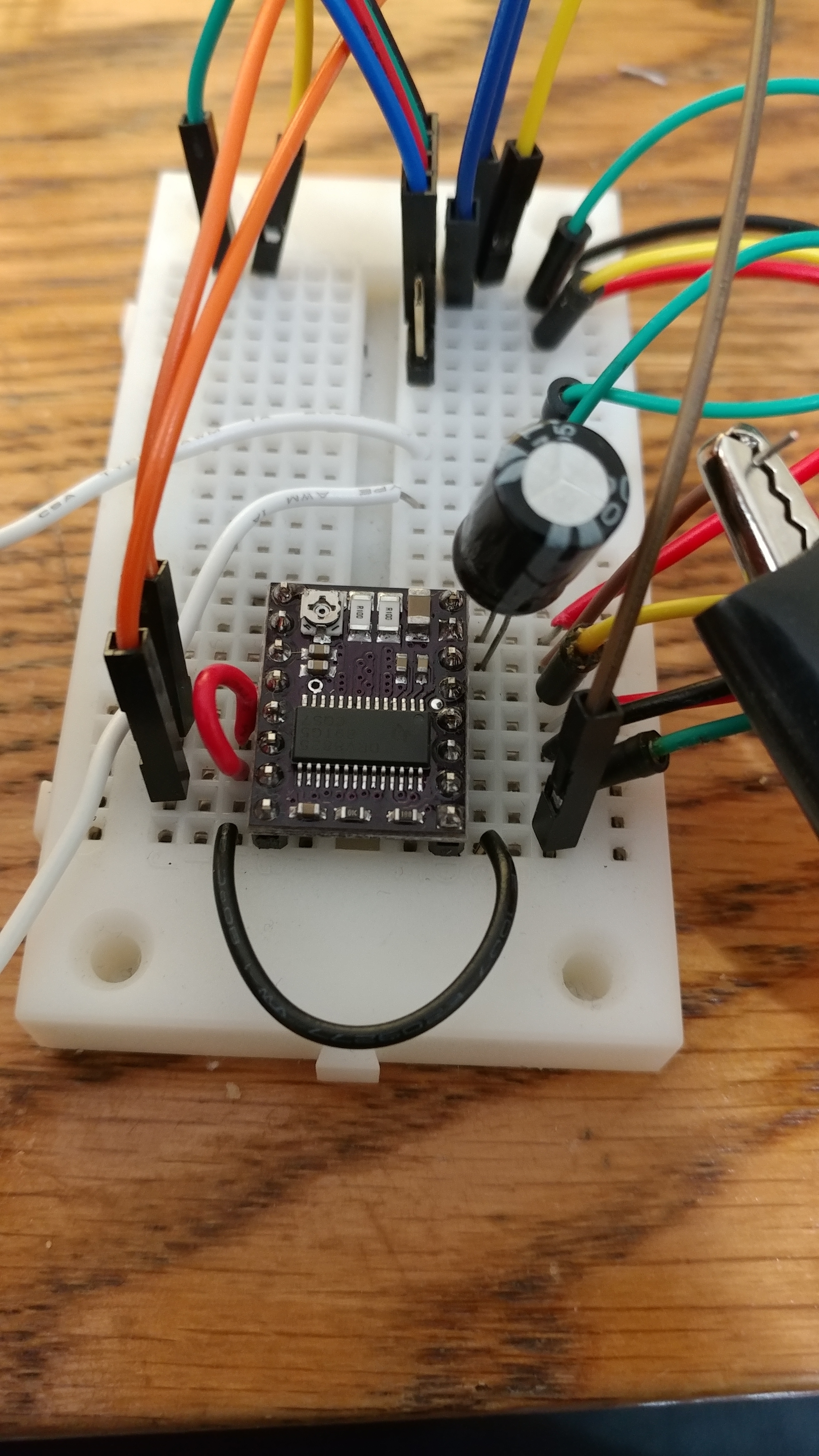
I’ve set Vref to 3.3V. I’m not sure what you mean by both sides of the DRV8825 “Carrier”, I assume that’s the Driver board itself? I’ve attached pictures of my setup.
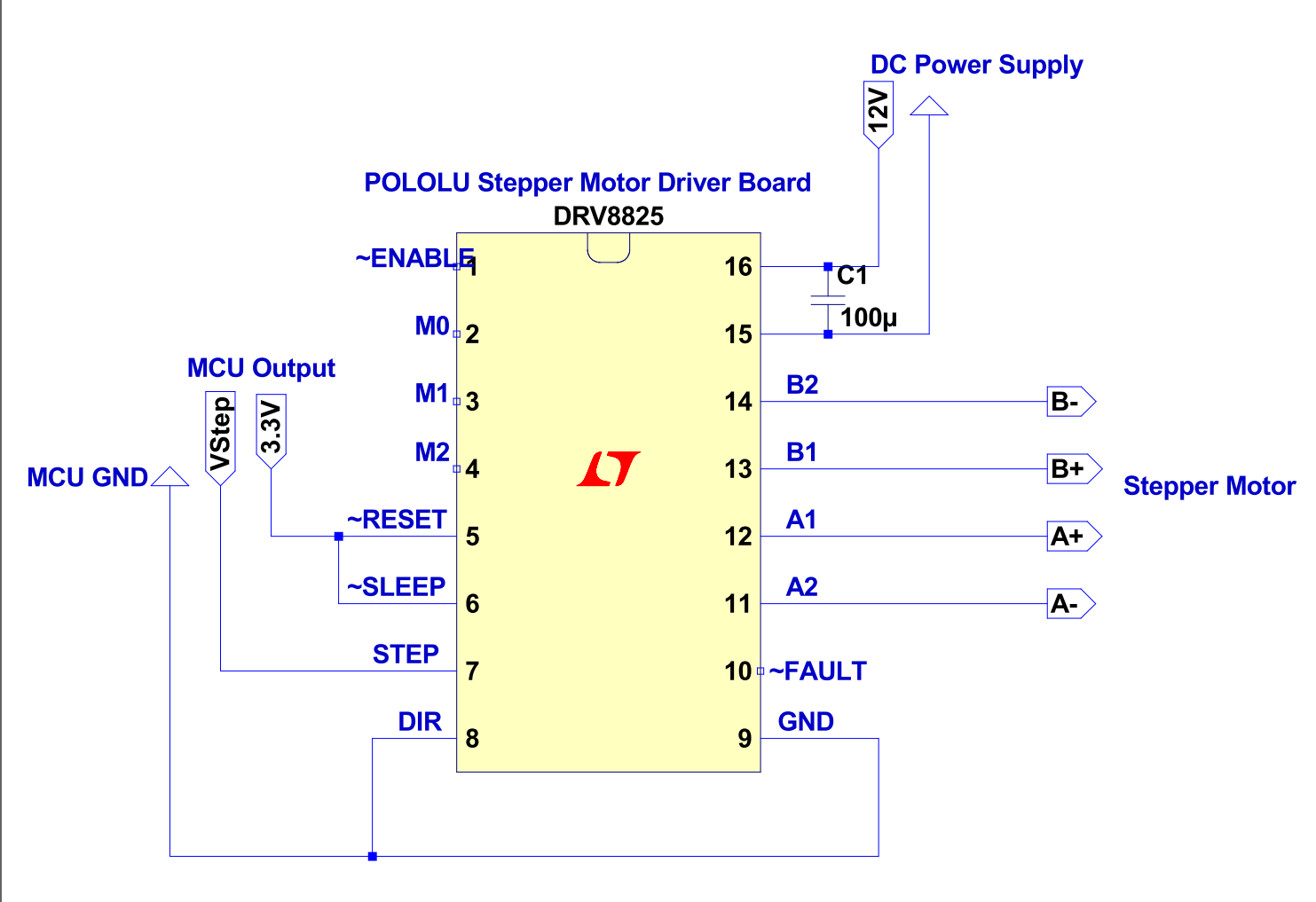
Here’s the Schematic. I used the “minimal wiring diagram” on the product page to make connections.
I’ve tested the driver and motor again with these settings …
Power Supply: 12VDC
MCU Ref Voltage: 3.3VDC
Step Signal: 3.3VDC
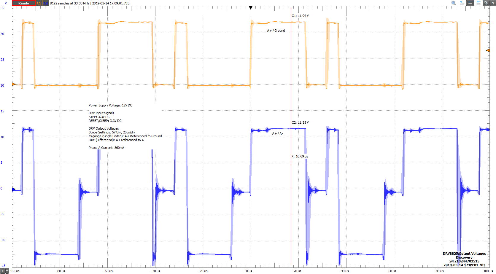
The resulting current (measured with DMM in series with Phase A) is 360mA, with current limiting potentiometer barely turned as seen in setup image above.
However, using a scope I see the voltage across Phase A flickers between +/- 12V at a rate of about tens of microseconds (see scope output image).
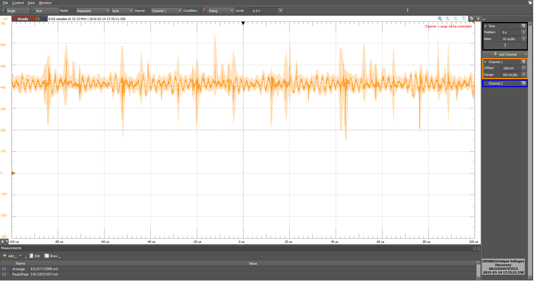
The Test Point Voltage on the board is shown below is about 400mV, although there is a lot of noise riding on it.
The Motor sounds like its on but does not move, even when I send a 0.5Hz step signal to the driver (3.3V HI/ 0V LO). A few questions …
- Can this imply the motor itself is damaged and not the board?
- What should output Voltages across phases, and current through phases look like for no stepping?
- Are my measurements affecting the readings?
Thanks for the help!!
Thank you for the pictures. Yes, I asked for pictures of both sides of the DRV8825 board; pictures of the bottom will show if all the solder joints look good.
I cannot tell much from your close up picture of your connections since the wires go out of frame. Can you also post a top-down picture showing the entire setup and all of the connection points?
It is not very useful to look at the voltage on the driver’s outputs. When the driver is not getting any step signal the current on the outputs should be steady; when it is stepping the current will switch and look like a sign wave depending on the microstepping mode.
I think you mistook what I meant by VREF voltage; that is the reference voltage on the DRV8825 board that is used to set the current limit (not your logic level voltage). VREF can be measured from the test point you mentioned, so it seems like your current limit is currently set to around 0.8A. To get a limit of 1.5A (like your motor is rated for) you would set your VREF voltage to 0.75V. You can follow the directions in the video under the “Current limiting” section of the DRV8825 product page to set the VREF voltage.
Please note, we rarely see a stepper motor break, so that seems unlikely.
-Derrill
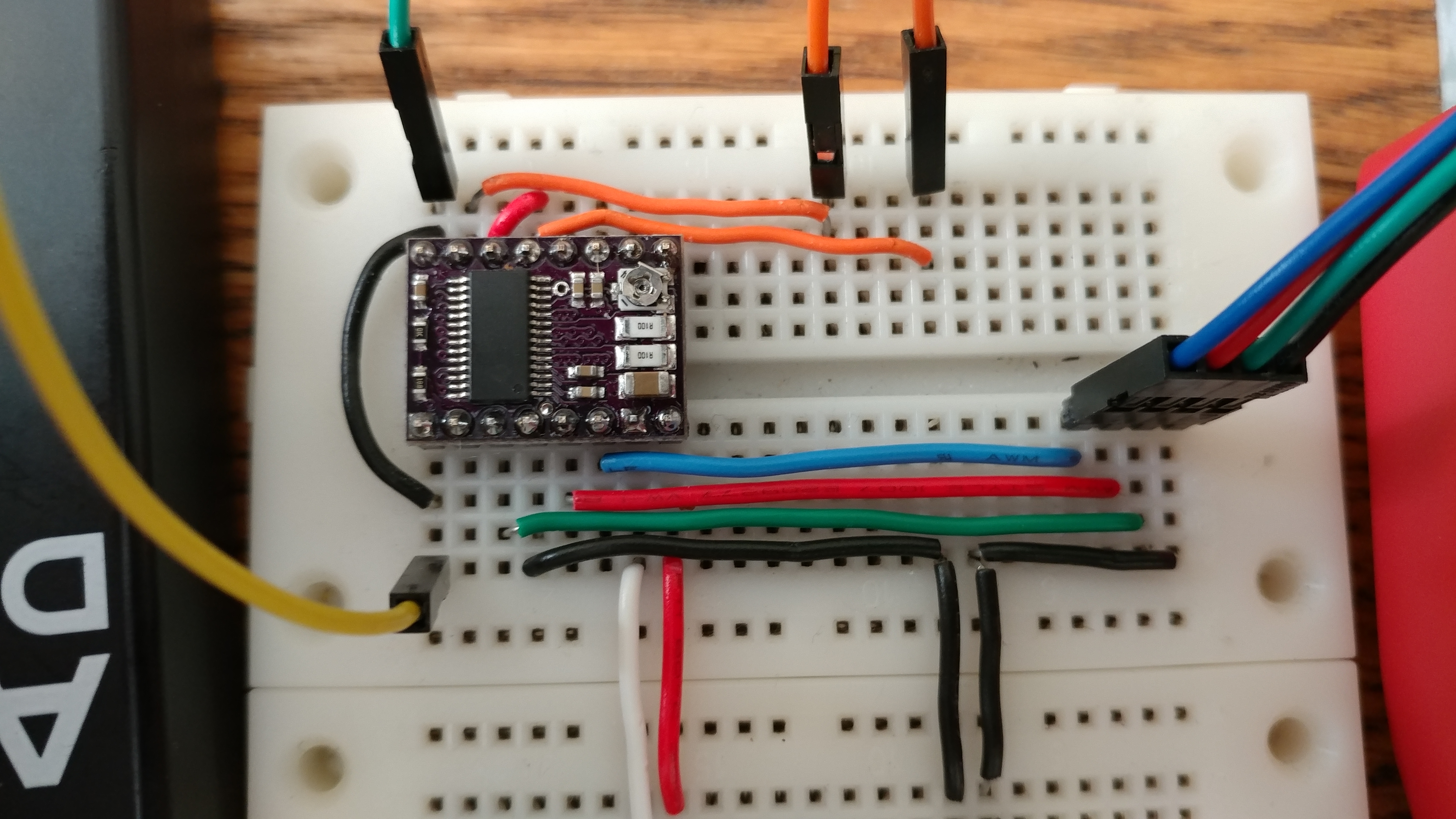
So I cleaned up the wiring a bit. Shown below.
The Red (Positive) and White (Negative) wires going offscreen connect to a 12VDC Switching Power Supply.
Black Wires going offscreen connect a Digital multimeter in series to measure current.
The two orange and one green wires up top connect to MCU, Right orange being 3.3V, left orange being Step Signal, green being ground.
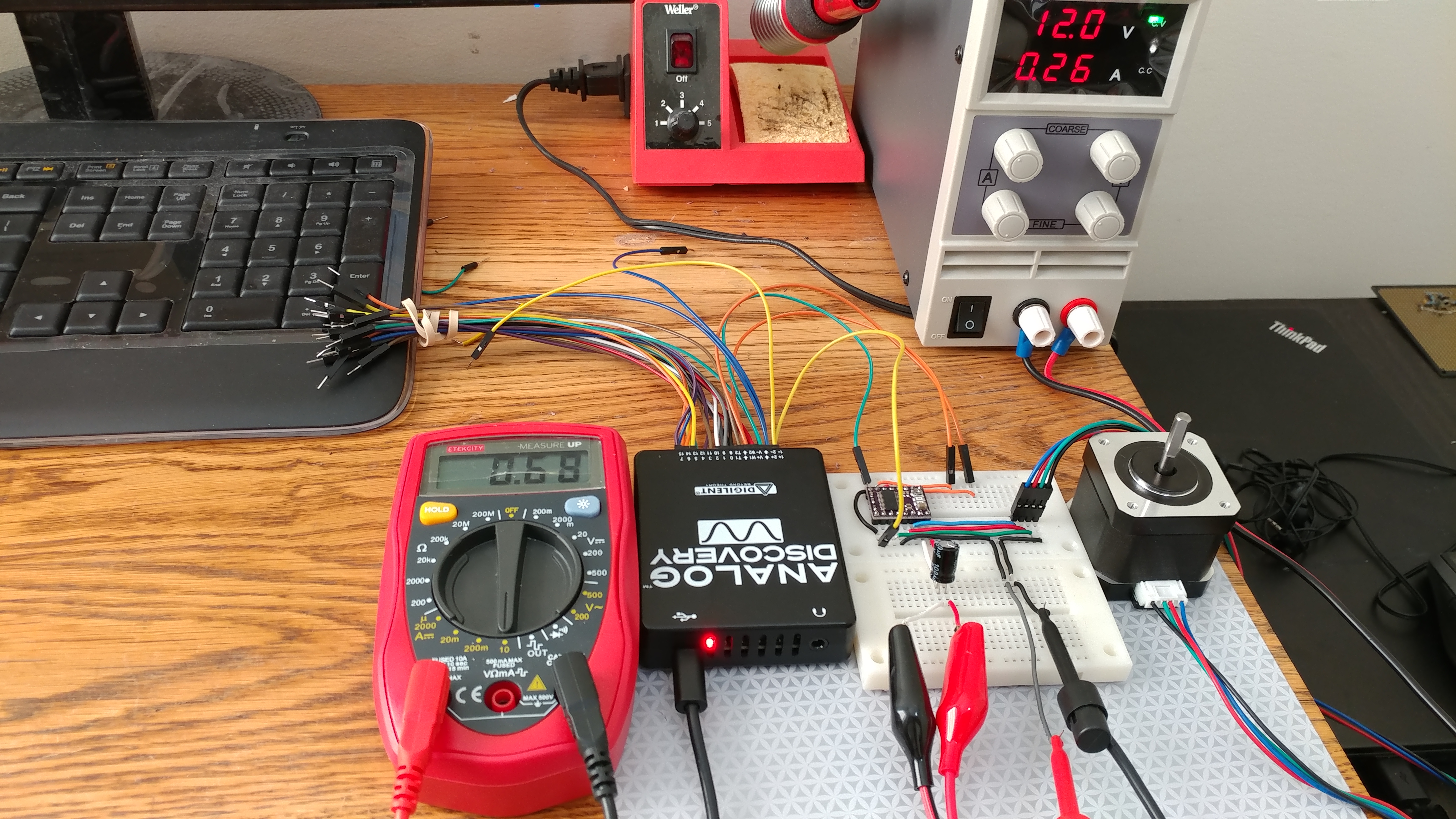
Here’s another image of the whole setup.
I use the analog discovery to probe the VREF test point, and get about 760mV when NOT stepping.
Problem is, I don’t see the current change using the multimeter at all when I step the signal even at very low speeds.
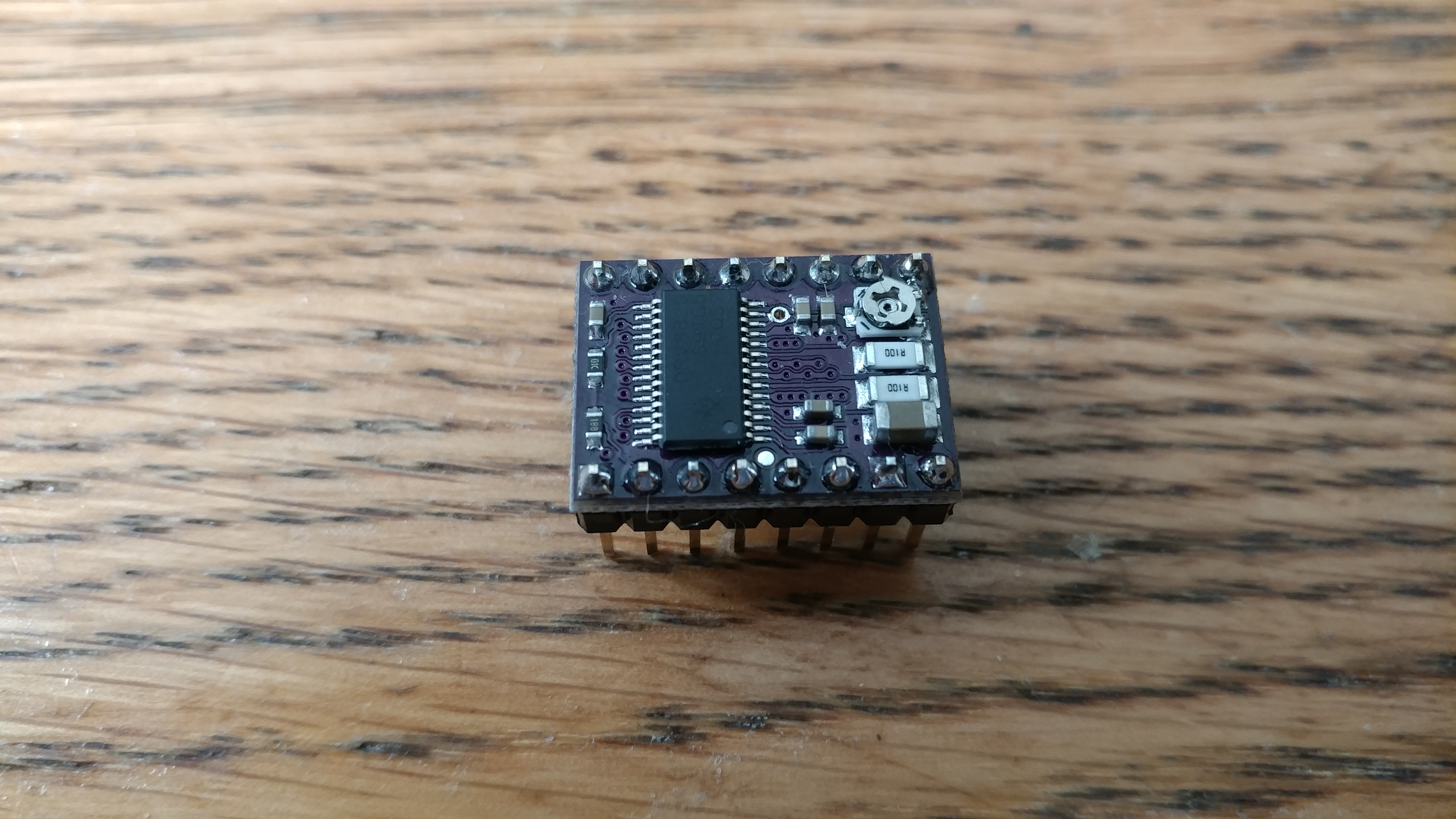
Images of soldering on DRV8825 carrier
Beneath the board. Using header pins so cant really see anything.
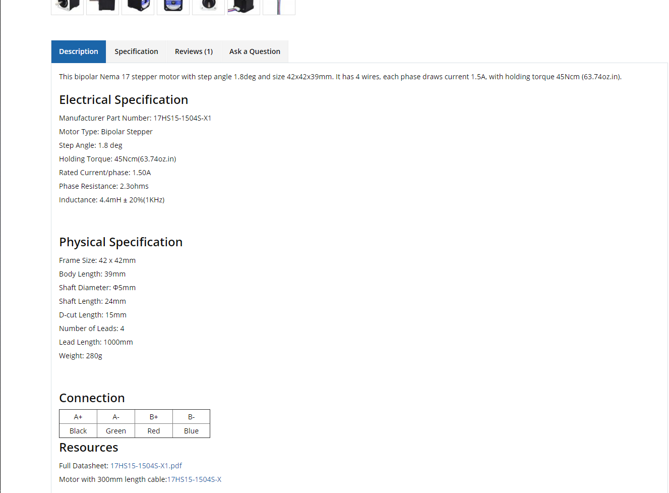
Motor uses these connections (From product page)
Have I damaged the DRV8825? Thanks.
Hi Derrill, I’m pretty sure I fried the DRV8825 board. I ordered a replacement board which seems to work fine with the same motor and same setup/wiring. Thanks for the help!
1 Like