Stepper 1209 not working with slow speeds using 8824

Hi, I need some advice on my project. I’m building a 3 axis omniwheeled robot using 3 pololu 1209 stepper motors (which are rated 1A, 2.7ohm) and 8824 drivers using a 12V 5A power source.

When driving the motors at moderate step frequencies of 1000Hz and above without any load, just the wheels, they run smooth, but at slow speeds, say 1 Hz, movement is erratic at regular intervals. Like brrrrrr click, brrrrr click, brrrrr click (etc). Microsteps are working during the brrrrr phase, but jumps ahead after being silent for a sub-second and clicks a multiple of microsteps as if it’s catching up after a short break.

I checked a lot so far:

  • Pwm signal is OK and regular
  • Varying duty cycle
  • Varying current setting
  • Using microstepping 1/4 through 1/32
  • Using pwm via hardware and software (beaglebone)

I’m currently in doubt if the 8824 is actually working at slow speeds with this motor. There are some sparse sources on the internet pointing into that direction.

Any advice here? Should I use the more common 4988 perhaps?

Some more observations, I’m now at 1/16th micro stepping mode, and noticed only the first 8 microsteps the steppers are stepping, but then the stepper jumps forward with the next step, and the next 8 microsteps nothing happens.Then the cycle repeats. I’m now thinking at higher speeds this gets unnoticed.

Also of interest, here’s the python code I’m using on the beaglebone:

[code]#!/usr/bin/python
import Adafruit_BBIO.PWM as PWM
import time

#PWM.start(channel, duty, freq, polarity)
PWM.start(“P8_13”, 50, 1)
time.sleep(60)
PWM.stop(“P8_13”)

time.sleep(1)

PWM.start(“P8_13”, 50, 5000)
time.sleep(10)
PWM.stop(“P8_13”)

PWM.stop(“P8_13”)
PWM.cleanup()
[/code]

So just run at 1 Hz for 60 seconds using a 50% duty cycle pwm signal. I’ve checked the pwm signal with en LED, it’s really 50% duty cycle.

Still wondering what could be wrong.

Hello.

Can you tell me more about your setup? What do you have the current limit set to? Can you post a video here that shows the behavior you are describing?

The duty cycle of the signal is not very important, so long as the driver IC has time to register the HIGH pulse and LOW between pulses (a couple of microseconds in both cases). A 50% duty cycle square wave should be fine, especially at a low speed.

-Nathan

Hello Nathan,

Thanks for your feedback! Much appreciated here.

  • My setup is 3 DRV8824’s driving 3 1209 steppers.
  • The drivers are wired according to the minimal wiring diagram, see pictures attached. All leads are soldered (though not visible in the picture), can’t find any shorts. I’m currently only using one driver for one motor as you can see in the picture.
  • The Vref voltage is set at about 1V, which equates to 0.61A
  • I’ve a 12V 5A DC source, which indeed delivers 12V to the VMOT pin when measured
  • DIR pin, Reset, Sleep, and micro stepper pins are connected to the +3.3V rail
  • Ground is connected to the Beaglebone

Will try to add a video in the next post.

And here’s the video. The 8824 driver is setup in 1/16th microstep mode in this video. In the background you can see the LED of the STEP signal blinking at 1 Hz. Barely visible is the stepper motor stepping, but you can feel it does. After 8 microsteps it suddenly jumps forward, and then 8 steps nothing happens, apart from small vibrations but no actual steps as far as I can feel or see. The holding torque is quite substantial as well, so my reasoning goes that current setting is large enough to turn the motor in micro stepping mode.

I’d almost think something is wrong inside the driver (like if part of the H-bridge is malfunctioning and not able to drive negative currents or something like that). That’s assumption though. All three drivers show the same behaviour on all three motors.

Any thoughts on this or suggestions?
VID_20160302_190504694c.mp4.zip (780 KB)

I do not see any obvious problems with the way your system is set up. The incremental torque the motor produces per microstep falls rapidly as the number of microsteps increases and it looks like that could be what you are observing. You can read a little bit more about why this occurs on this web page. You might try testing in full step mode and then trying finer microstepping to see if the behavior gets worse as the number of microsteps/full step increases.

Your current setting is still a bit below what your driver and motor should be able to handle, so you should be able to get a little bit more torque out of your stepper by increasing the current setting, though very slow 1/16 microstepping might still not work well.

-Nathan

Okay, thanks again for the suggestions. I’m aware of the decrease in torque due to micro stepping. Just had a brainwave, I’ve measured voltages across the motor pins (although current would be preferred, but more difficult to measure). Now I’m at 1/8 step, and here are the results (bare in mind + and - might be arbitrary).

pulse 1: +1.26 +1.61 jumped, note voltage change from 0 to +1.26V (see pulse 32)
pulse 2: +1.26 +1.51 barely moves
pulse 3: +1.26 +1.36  barely moves
pulse 4: +1.26 +1.36
pulse 5: +1.40 +0.91
pulse 6: +1.52 +0.61
pulse 7: +1.65 +0.29
pulse 8: +1.69 +0.00
pulse 9: +1.58 -1.25 jumped, note the voltage change from 0 to +1.25V
pulse 10: +1.48 -1.25 barely moves
pulse 11: +1.34 -1.25 barely moves
pulse 12: +1.14 -1.25
pulse 13: +0.90 -1.43
pulse 14: +0.59 -1.59
pulse 15: +0.28 -1.70
pulse 16: +0.00 -1.73
pulse 17: -1.26 -1.64 jumped, note the voltage change from 0 to -1.26V
pulse 18: -1.26 -1.64 barely moves
pulse 19: -1.26 -1.54 barely moves
pulse 20: -1.26 -1.38
pulse 21: -1.40 -0.92
pulse 22: -1.56 -0.61
pulse 23: -1.65 -0.29
pulse 24: -1.70 +0.00
pulse 25: -1.62 +1.25 jumped, note the voltage change from 0 to +1.25V
pulse 26: -1.51 +1.24 barely moves
pulse 27: -1.36 +1.24 barely moves
pulse 28: -1.16 +1.25
pulse 29: -0.90 +1.43
pulse 30: -0.59 +1.59
pulse 31: -0.28 +1.69
pulse 32: +0.00 +1.73
(all values in Volts of course, first value is measured across pin A1-A1, second value is measured across B1-B2, I'm referring to the minimal wiring diagram for the location of the A1, A2, B1, B2 outputs )

So the output to the stepper shows - at least for me - unexpected voltage/current jumps. The voltages measured are very consistent, a ran this test multiple times writing down the values (at 0.25Hz this time to be able to write down the values). Looks like something is messes up inside the driver? I have three drivers, all showing these jumps when micro-stepping. They are md20b series (if that’s of use). I just ordered three A4988’s, I wonder how these will perform. You might consider RMA to check the 8824’s I have?

It does not sound like the drivers are malfunctioning, especially since all three give the same behavior.

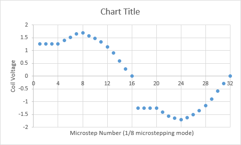
I plotted those values and (ah-ha!) it looks like your driver is having trouble maintaining a voltage below 1.26V when the driver is in slow decay mode (which is the mode the driver operates in when increase the coil current for the next step). That plot should approximate a nice sine wave, but right now, the power cannot switch on and off fast enough in slow decay mode to do that. Using a lower voltage power supply (like 9V) will allow the driver to use a higher PWM duty cycle to step the input voltage down to the voltage required to drive the coils, which should improve the performance. Also, increasing the current limit would increase the peak voltage of that sine wave, so the problematic region would be smaller. The A4988 will provide a little more current than the DRV8824, but I’m not sure if the switching performance is any better. The DRV8834 stepper driver will work with lower voltage power sources than the DRV8824 and A4988, so you also might consider that.

Also, this blog post discusses using diodes in series with the stepper motor to raise the threshold voltage at which current flows, which seems to have worked OK for them.

-Nathan


Nice graph, thanks for taking the effort! I just checked with a 9V power supply and increasing current a bit to see what’s possible without a heat sink - chip getting very hot now, and noticed slight improvement (and also high frequent noises at some steps also). Not satisfactory though, 3 steps are missing and still jumping.

Kind of stunned here as I did not expect the driver to be limiting in my design. I’m apparently at the borders of what’s possible with the 8824 (max current, minimum voltage) and still missing steps. I was under the assumption that a higher voltage would be a plus (forcing current through the coils faster due to inductance of the coils at higher frequencies), and a chopper limiting the current once max current is reached. I wonder what is the limiting combination of factor(s) of the driver that I overlooked? Is there some way to tell the 8834 is better, but why?

My reasoning goes like this with your explanation - very sketchy though (e.g. ignoring inductance: maximum current is 0.75A for this driver without heatsink. Given a minimum operating voltage of the driver of 8.2V, and a resistance of 2.7 ohm for one of the stepper motor coils, I’m able to deliver 3A to a coil. This needs to be chopped down by the driver to 0.75A, or 25% of the 3A. Maybe I’m off by some factor due to other losses, but is there a minimum chopping duty cycle that is giving me trouble? I see 3.75micro seconds minimum in the spec sheet, combined with a PWM frequency of 50kHz (or 20 micro seconds period). This would be a minimum duty cycle of less than 18%. That would be in the order of my 25%…hmmm.

The 8834 has similar specs, apart from the operating voltage indeed. To make sure: driving with low voltages gives less power at higher speeds due to inductance of the motor coils, but is that the only trade-off to consider? Lower voltages is a plus for me I have to say, I’m planning to use batteries later on.

Thanks - Joseph

Re-reading your reply (Nathan), and the blog you refer to, I’m now seeing two possible reasons for the observed behaviour:

  1. The 12% minimum voltage to the stepper motor with respect to the supply voltage (I calculated 18%) due to blanking time.
  2. Slow decay mode when increasing current to the next step.

I’m thinking reason 1) is not the issue since my measurements show that skipping steps does not occur when the current is decreasing. Also, I found the A4988 datasheet exactly describing the observed behaviour, indicating the 2nd reason for missing steps: “For some applications where microstepping at very low speeds is necessary, the lack of back EMF in the winding causes the current to increase in the load quickly, resulting in missed steps. This is shown in Figure 2. By pulling the ROSC pin to ground, mixed decay is set to be active 100% of the time, for both rising and falling currents, and prevents missed steps as shown in Figure 3.”


So this exactly fits the behaviour I see. I now see all mentioned drivers in this thread have been setup using the same slow / mixed decay mode, which I now believe can result in the same behaviour in all drivers for slow speeds in micro stepping mode?

Apart from adding diodes as mentioned, though less tempting, I’m also contemplating to put the DRV8824 in mixed decay all the time by grounding pin 19 (DECAY) and see what happens. Unfortunately, that pin is not very accessible compared to the A4988 and DRV8834. I wonder if that has been done before, and what is the experience?

It sounds like you are mixing some information between the datasheets for the DRV8824 and A4988 that is not the same for both chips. Although the general decay modes are similar, the inputs to the DRV8824 are different than the A4988 and grounding the DECAY pin (pin 19 on the DRV8824 IC package) will place the DRV8824 into slow decay mode (discussed in section 8.3.3 of the DRV8824 datasheet). Our carrier board leaves that pin floating, which places the driver into mixed decay mode by default. Pulling the pin to logic high will place the board in fast decay mode.

The results of using a full fast decay mode cycle are also discussed in the “DRV8825 missing microsteps” blog post I mentioned previously. In general, it seems like it could be worth trying since, although it made his motors very noisy.

By the way, the datasheet for the DRV8824 only talks about decay mode changing between rising and falling current periods of the step cycle in mixed decay mode, so you can presume that if you place the driver into slow decay or fast decay mode, that decay method will be used throughout the entire step cycle. Also, since the datasheet does not mention any way to change the slow rising, mixed falling decay behavior, you can presume that there is no way to get mixed-decay when current is rising on the DRV8824 (though that would probably help your problem if it were possible). The graph from the A4988 datasheet you posted does seem to be applicable to your problem and it looks like it is possible to run the A4988 in “full step cycle” mixed decay mode.

-Nathan

Thanks again Nathan for pointing that out about the difference in DECAY and ROSC pins and their effect on decay modes. Probably need several re-reads of the other post to fully understand what’s being said, but it’s getting more clear. Decay modes and their application is also still some of a mystery - did not foresee to dig into this that much though.

I just looked into the data sheets again, and came up with following table:

current up current down A4988 normal operation Slow Decay Mixed Decay A4988 ROSC to ground Mixed Decay Mixed Decay 8824 normal operation Slow Decay Mixed Decay 8824 DECAY to ground Slow Decay Slow Decay 8824 DECAY high Fast Decay Fast Decay

The 8824 data sheet is a bit ill-described on page 13, but I figured in normal operation when current goes up, Slow Decay is used in the end.

Mixed Decay is in both data sheets described as beginning with Fast Decay, then going to Slow Decay, only the time when this changes during the PWM cycle is different.

The DACAY or ROSC pin have different meaning for the DRV8824 or A4988 indeed (thanks again pointing this out). With the explanation in the A4988 data sheet which I copied in my previous post, we need Mixed Decay all the time for slow micro stepping, but now I see this is not possible to set via the DECAY pin in the 8824.

I noted the mention of the noise the 8824 can produce as well. Taken that into account, the A4988 looks like a safer bet I’d day compared to the 8824. I’ve no clue yet about the 8834. The 8834 again has a different approach to Decay Modes. I’m tempted to try the 8834 as well given your suggestion earlier, but in the light of another Decay Mode approach, does that still driver still have the advantage?

- Joseph

There are likely tradeoffs between all of those drivers. It sounds like you have ordered some A4988 boards, so you might just see if those work acceptably.

-Nathan

Ok, so I’ve tested the 8834 (they came in earlier), and results are way better. Here’s measurements of one phase with moderate current/voltage setting (say somewhat halfway the driver’s abilities) :

(Vmot = 4.5 V, Current Limit = 0.5A, step = 0.5 Hz)
0
-0.51
-0.97
-1.26
-1.37
-1.24
-0.96
-0.5
0
0.52
0.97
1.26
1.38
1.24
0.95
0.5
0

Graph:

So very nice sine wave, no jumps there! Currently testing what speeds can be achieved using different currents, voltages and micro step resolutions. Still plan to test the A4988 as well.

I am glad to hear you have a setup that is working better. It would be interesting to see how the A4988 and DRV8834 compare to each other at the same input voltage and current limit. Of course, you would need to increase the voltage to the operating range of the A4988.

-Nathan

Ok, so I’ve studied theory of an LR network, and came up with following to understand what is happening when using the DRV8824 in microstepping mode.

I came up with the following. The motor can be modelled as an L/R network with a resistor and inductance in series, in which the resistance is both the motor resistance Rmotor and Rds(on). In general, the formula for such an L/R network given a step response input voltage is given by:

Vstep(t) = Vdifferential * (1-exp(-(R/L)*t))

Where Vdifferential is the differential voltage, which equals the motor voltage Vmot in initial state.

When the voltage is removed again, the voltage across the L/R network is given by:

Vdecay(t’) = Vdifferential * exp(-(R/L)*t’)

So both are essentially exponentials with time constant R/L and amplitude given by the voltage differential. For the first PWM with duty cycle given by the blank time Tblank, the voltage across the stepper motor is:

V1 = Vmot * ( 1 - exp(-(R/L)*Tblank))

Then using slow decay, the voltage decays to:

V2 = V1 * exp(-(R/L)*Toff)

If this voltage is not decayed to zero volt, e.g. when Toff is too small, we end up with a residual voltage. With the next PWM cycle, voltage is again increase by approximately the value of V1, and the residual voltage is approximately twice the residual voltage of the first PWM cycle. This voltage increase continues until equilibrium state is reached.

An estimate of this can be calculated by linearising both exponential functions around the voltage in this equilibrium state. This equilibrium state is when the voltage increase due to Tblank is equal to the voltage decrease of Toff. Both are given by the linearisation of the first to formulae:

Vincrease(t) ~ (Vmot - Veq) * (R/L) * t

Vdecrease(t) ~ Veq * (R/L) * t

In equilibrium state Vincrease(Tblank) equals Vdecrease(Toff):

(Vmot - Veq) * (R/L) * Tblank = Veq * (R/L) * Toff

or

Veq = Vmot * Tblank / (Toff + Tblank)

So the equilibrium state depends on the motor voltage, and the ratio between Toff and Tblank, and is independant of R/L. The DRV8824 has a minimum duty cycle (Tblank) of 3.65 microseconds. Given the PWM frequency of 50kHz (or 20 microseconds period), the remaining time (Toff) the motor voltage is switched off is then 16.3 microseconds. The minimum motor voltage is 8.2V for this driver, which results in a minimum voltage of:

Veq = 8.2 * 3.65 / 20 = 1.49V

That’s 18% of Vmot. It’s also possible to simulate this behaviour using the first two formulae, giving the graphs attached / below. Within about 6 msecs, equilibrium state is reached.

So, that would explain the behaviour seen? The issue with the 8824 driver is the slow decay mode used when increasing current during micro stepping, combined with the rather high minimum duty cycle given by Tblank.

Now the tricky thing here is: why is the DRV8824 advertised as being able to do micro stepping up to 1/32 steps? I came to the conclusion the driver is not able to do this as it is hard-wired and not configurable to another decay mode needed for micro stepping.

The microsteps still get you smoother motion if you are going faster, and if you want to be able to stop at arbitrary microstep position, then you need to use the fast decay mode. Here is one way of putting the driver into fast decay mode:

-Nathan