I bought a mini pushbutton power switch board, and I’m trying to wire it so I can re-use the push-button as a sensor to an Arduino so it can read the button state and perform a controlled shutdown.
My goal is that when the Arduino is off, an external pushbutton wired to the A pin will short to ground, turning the Arduino on. Then, when someone presses the external pushbutton again, the Arduino will register the key-press, do some internal cleanup, and then set OFF pin high to turn itself off.
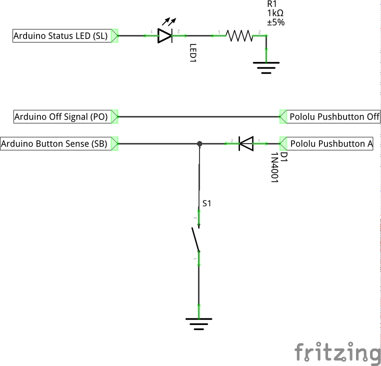
This is the simplest way I thought I could accomplish this behavior:
I found I had to add the diode because when the pushbutton board latches on, the A pin appears to stay shorted to ground, causing the Arduino’s SB pin to always register low, regardless of the external pushbutton state, meaning the Arduino could never tell when the external pushbutton was pressed again.
However, this circuit still doesn’t work. The problem I’m now having is that the pushbutton board immediately turns “on” and stays stuck “on”. Even setting the OFF pin to high has no effect. How do I fix this circuit?
I noticed one thing about your circuit. It should not be used if VIN is higher than 5V, since the Arduino I/O pin will be exposed to VIN whenever the switch is turned off. If you want to use a higher VIN voltage, you could use a couple high value resistors in a voltage divider. (Two 100k resistors worked when I tried it here). Besides that, the circuit should work for measuring the voltage on the A pin. However, when the switch is on, the voltage on the A pin will be partway between VIN and GND, so it is possible that your Arduino would not recognize that voltage as a high. You might try using one of your Arduino’s analog input pins instead.
You mentioned that now you are having trouble turning your switch off at all, which I would not expect. Can you turn it off with the on-board button? Does it function normally if you remove it from your circuit entirely? What input voltage are you using? Could you post a picture of your physical switch circuit?
Yes, my VIN is 12V, which probably explains why the input pin I was initially trying to measure with is now fried. Oddly, it still works fine as an output so I can reshuffle my project’s pins to work around the damage. You should really mention in the docs that A shorts to VIN, because that’s unclear.
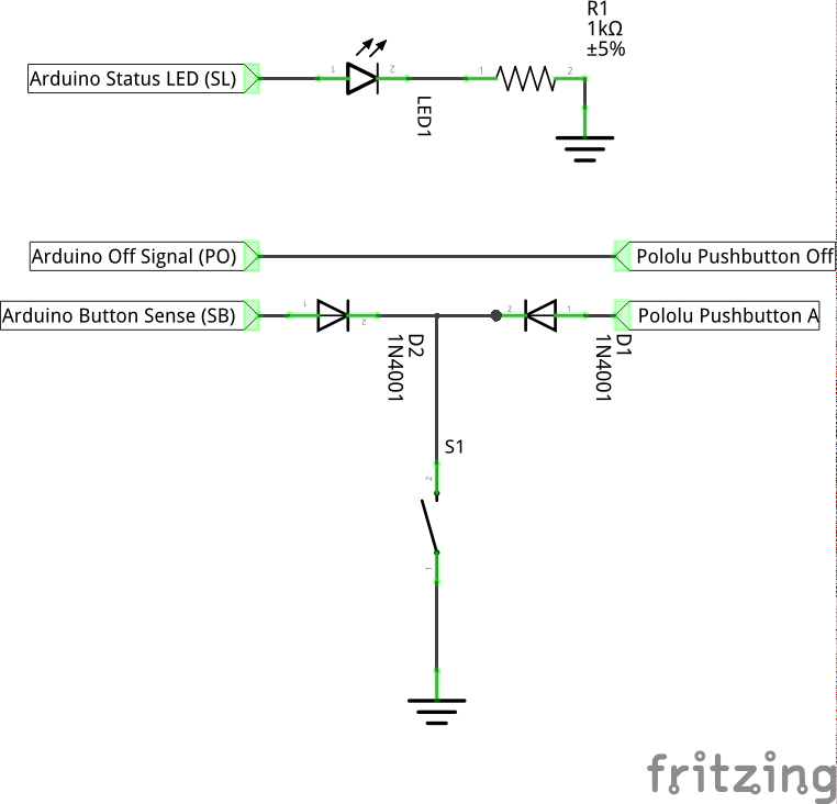
In any case, I figured out the problem. It seems that when unpowered, the Arduino pins act like a short to ground, which activated A and caused the power switch to get immediately stuck on as soon as VIN was applied. Adding a diode to isolate the pin from A fixed the problem. This is the correct circuit:
I am glad you got it working! Thanks for posting your updated schematic. In case you weren’t already using it, enabling the pull up resistor on the Arduino pin you are using to read the A node should help you get a clean high or low reading.
By the way, you used the term “short” incorrectly. That is not correct for the A node or the unpowered Arduino pins. The A node is pulled up to VIN by a resistor when the switch is not on. We plan to update our documentation for our push button power switches with more tips, but in general you should be careful about assuming that an unspecified pin is at a safe voltage.
In your response to Cerin’s query above you state that “when the switch is on, the voltage on the A pin will be partway between VIN and GND, so it is possible that your Arduino would not recognise that voltage as high.”
I have a similar situation but am using a Baby O instead of an Arduino.
The intention is as follows:
The first push of S1 (remote momentary push button) will:
a) Pull the Mini SV A pin to GND
b) Supply +9 VDC to the Baby O VIN
c) The Baby O will then run its sequencing program
d) On completion of the sequence the Baby O will send a pulsed output (via pin PD0) to the Mini SV OFF pin thus powering down the Baby O.
Should S1 be pushed a second time (whilst the sequencing program is running) the consequence will be:
a) The Mini SV will see this as a second initialisation command and do nothing as it is already supplying +9 VDC to the Baby O VIN.
b) The Baby O which is now running, will sense the second push of S1 (via pin PD1) and will stop the sequence, write to flash, then send a pulsed output (via pin PD0) to the Mini SV OFF pin thus powering down the Baby O.
My questions are:
a) Will the Baby O (pin PD1) be reliably pulled to GND on the second push of S1 given that S1 is simultaneously pulling to GND +9 VDC from the Mini SV pin A and +5 VDC from Baby O pin PD1, or will it see a voltage “partway between VIN and GND” ? (Please refer to attached diagram for clarity).
b) Given that the Mini SV supply will be +9 VDC (the lower end of its 4.5 to 40 V operating range) can I assume that its startup-state will be OFF after a battery change?
I do not expect using a Baby Orangutan instead of an Arduino to have any significant impact on how well the circuit Cerin posted works. As you quoted, when the switch is on, A will be partway between VIN and GND, so your external button will not be trying to pull down a 9V source. In addition, if you use the internal pull-ups on the Baby Orangutan, PD1 will also only be pulled-up to 5V and pushing the button would not directly connect the 5V source to ground.
When using an input on the lower end of the power switch’s range, it is less likely that it will turn on when power is applied. but we cannot guarantee that it will always power on in one state or the other.
With the Baby O pin PD1 configured as an input and pulled HIGH via the internal resistor, would PD1 be pulled LOW (enough to trigger a state change) if S1 was pushed a second time?
Also can you please confirm that pushing S1 a second time will not cause a state change to pin A of the Mini SV?
I have re-attached my proposed diagram for reference.
Since you have your button directly connected between ground and the node with both diodes, PD1 will be directly connected to ground when the button is pushed. Pulling the A node to ground will not cause the pushbutton power switch to turn off.
As I mentioned before, your circuit is essentially the same as Cerin’s, so it should work the same.