Ok, thanks for your help!
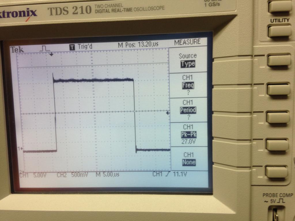
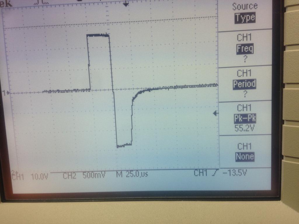
Here is an image of the oscilloscope screen when I bypassed the inductors.
Basically the same signal, but it is noisier.
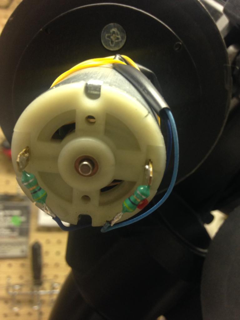
To get this oscilloscope reading, I connected the PWM outputs of the DRV8801 directly to test leads, connected the test leads to the motor connections, and clipped the oscilloscope leads to the test leads. I didn’t take a picture of that, it’s a lot of wires and didn’t seem useful. But I can send a pic if you want…
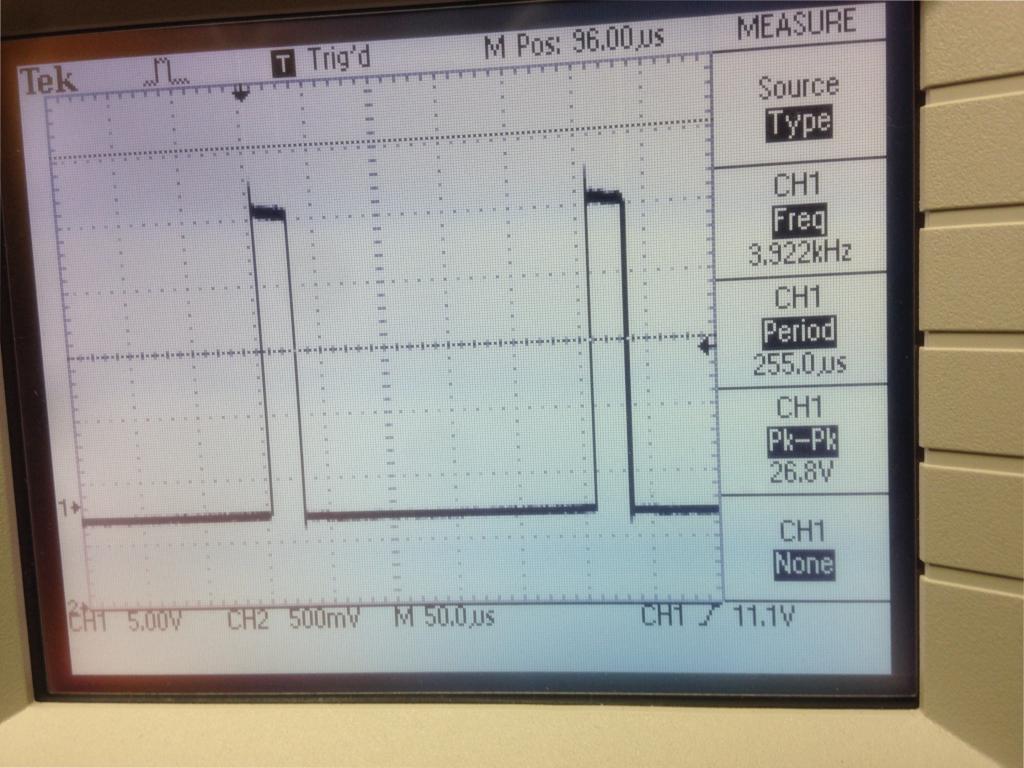
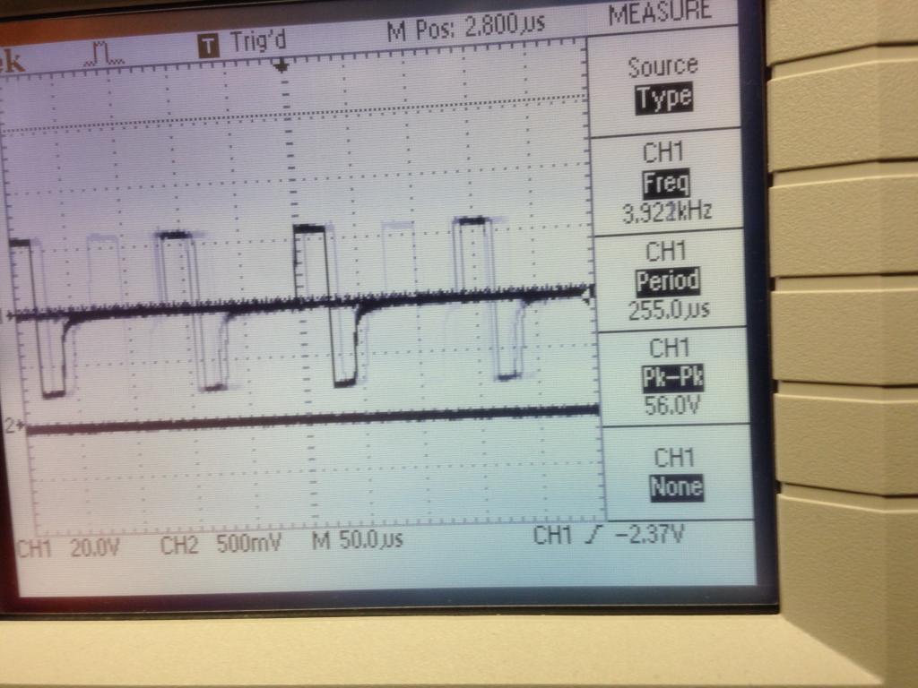
For the other readings, I connected the oscilloscope probes inline with the motor outputs of the DRV8801. The connections to the machine are via a DB25 cable, so I connect to a DB25 breakout box I have inline with the cable connecting the controller to the machine.
As far as my overall setup, it’s a custom PCB I built. There’s a bunch of stuff in there that’s irrelevant to what we’re talking about here, and it’s kind of proprietary, so I don’t want to post it on a public forum. But I can PM you the circuit diagram if you want.
As far as the DRV8801 connections go, I’m sending a PWM signal from an Arduino. The Arduino normally outputs a 490 Hz PWM signal, so I have some code to modify the system clock to send the 3.9kHz signal. I expect you know all about how to do that, but I can send you a link explaining it if you want, and it doesn’t seem relevant to what’s going on here. But maybe it is - what do I know.
My connections to the DRV8801 are as follows:
VCC → 5 volts
BRAKE-> GND
SLEEP-> Arduino digital pin
DIR-> VCC
PWM → Arduino digital pin (PWM output)
GND-> GND
FAULT → floating
CS-> Arduino analog input pin
VMM → 24 volts
OUT- → motor negative
OUT+ → motor positive
GND → GND
So pretty straightforward…
I’ve probably left some things out and you probably have more questions, so would it make sense if we talked on the phone instead?
Thanks again.
- Dave